Op-Amp Absolute Maximum Ratings
In this article, "Op-Amp Absolute Maximum Ratings" will be explained in detail.
And the absolute maximum rating parameters listed in the datasheet of the Analog Devices, Inc. are mainly used as reference.
What is the Absolute Maximum Ratings of an Op-Amp?
The absolute maximum ratings of an op-amp is a specification to ensure that the op-amp does not break down during operation.
If the absolute maximum ratings are exceeded even for a moment, the op-amp is likely to be damaged, so it is necessary to check the datasheet first when using op-amps.
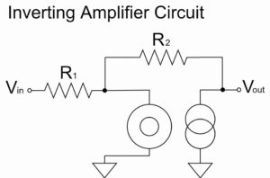
Also, to understand the op-amp absolute maximum ratings, it is better to know about an ideal op-amp beforehand.
Please refer to the following article for a detailed explanation.
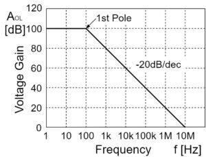
On the other hand, "electrical specifications" are also important. For the real performance of an op-amp, the electrical specifications should be checked in the datasheet.
For a more detailed explanation of the op-amp electrical specifications, please refer to the following article.
Op-Amp Absolute Maximum Ratings
The parameters for op-amp absolute maximum ratings are listed as shown below:
ABSOLUTE MAXIMUM RATINGS
Supply Voltage
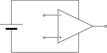
The supply voltage of the absolute maximum rating is the maximum value that will not be broken when a voltage is applied to the + and - power supply pins of the op-amp.
For example, if the supply voltage of the absolute maximum rating is specified as "36V", the op-amp will not break down if it is within the range of ±18, ±15, +36V, etc.
However, it is only a value that will not break down the op-amp, and must be within the operating supply voltage range of the electrical specifications to bring out the true performance of the op-amp.
Input Voltage
Common Mode Input Voltage
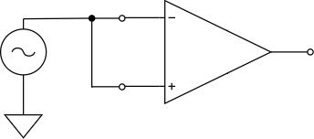
The common-mode input voltage of the absolute maximum rating is the maximum value that will not break down the op-amp when the input + and the input - of the op-amp are added at the same potential.
Often set to the maximum voltage range of the supply voltage, some device manufacturers simply refer to it as "input voltage" in their datasheets.
Differentical Input Voltage


The differential input voltage of the absolute maximum rating is the maximum value that will not break down the op-amp when applied between the input + and the input - of the op-amp.
Often set at "±supply voltage," polarity is not important.
For example, if the differential input voltage of the absolute maximum rating is ±30V, then even if the differential voltage between the input + and the input - of the op-amp is +30V or -30V, and the polarity is different, it is within the absolute maximum rating.
Temperature Range
Storage Temperature Range
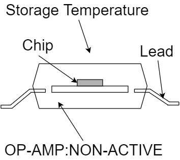
The storage temperature range is the range of ambient temperatures in air that will not break down the op-amp when power is not applied to it and it is not operating.
Operating Temperature Range
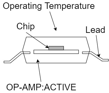
The operating temperature range is the range of ambient temperatures in air that will not break down the op-amp when power is applied to it and it is operating.
And it is smaller than the storage temperature range because heat is generated inside the op-amp during operation.
Junction Temperature Range
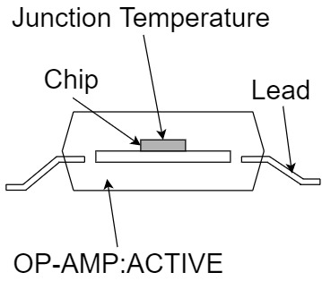
The junction temperature range is the temperature range of the internal junction of an op-amp that will not break down the op-amp when power is applied to it and it is operating.
Silicon semiconductors are more likely to break down at junction temperatures around 150℃.
The junction temperature range is usually the same value as the storage temperature range.
Lead Temperature
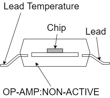
The lead temperature range is the temperature at which the op-amp pins will not break down when soldered.
The device manufacturer's datasheet is listed the soldering time and temperature as "10 seconds for soldering, temperature 300℃," etc.
Allowable Power Dissipation
The allowable power dissipation $P_{D}$ is the maximum power consumption that will not exceed the temperature at which the op-amp will break down.
(An op-amp in operation will break down if the power consumption turns into heat and the temperature inside the op-amp rises, exceeding the temperature range of the absolute maximum rating.)
Usually, the allowable power dissipation is specified at an ambient temperature of 25℃ unless otherwise stated in the datasheet, so the allowable power dissipation will be smaller at higher ambient temperatures.
Thermal Resistance
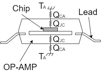
The thermal resistance is a parameter that indicates the resistance to heat transfer. The thermal resistances of op-amps are as follows:
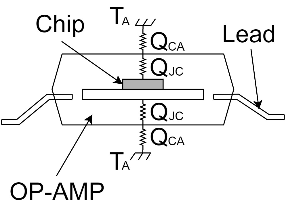
- $Q_{JA}$:Thermal resistance between the op-amp junction and the outside of the op-amp
- $Q_{JC}$:Thermal resistance between the op-amp junction and the op-amp case
- $Q_{CA}$:Thermal resistance between the op-amp case and the outside of the op-amp
etc.
*Thermal resistance $Q_{JC}$ may be considered separately for the "front" and "back" sides of the op-amp case.
As shown in the figure above, $Q_{JA}$ can be calculated by summing $Q_{JC}$ and $Q_{CA}$.
$$Q_{JA} = Q_{JC} + Q_{CA}$$
Furthermore, if the ambient temperature $T_{A}$ and power consumption $P$ are known, the junction temperature of the op-amp can be calculated as shown below:
Junction Temperature $T_{J}$ $=$ Ambient Temperature $T_{A}$ $+$ Thermal Resistance $θ_{JA}$ $×$ Power Consumption $P$
Thus, there is a close relationship between junction temperature, allowable power dissipation, and thermal resistance, which is important to fully understand during the thermal design of op-amps.