Best Pro Circuit/PCB Design CAD Software: 12 Comparison & Reviews
Nowadays, it is common practice to use CADs for circuit/PCB design in the professional field.
In addition, with the emergence of inexpensive circuit design CAD/PCB design CAD with open source or subscription licenses, they are now being used for hobby electronic work and for educational purposes by students.
However, various vendors develop and sell circuit design CAD/PCB design CAD, and you may be confused about which one to choose.
In this article, we will introduce "Recommended Circuit Design CAD and PCB Design CAD" that can be used mainly in the professional design field.
- Circuit Design CAD: Circuit CAD/Circuit Design Software/Circuit Layout Software/Circuit Making Software
- PCB Design CAD: PCB CAD/PCB Design Software/PCB Designer Software
Circuit Design CAD and PCB Design CAD are sometimes referred to by the above names.
What is Electrical CAD?
Types of CAD
- ElectricalCAD
- Circuit Design CAD (Circuit CAD/Circuit Design Software/Circuit Layout Software/Circuit Making Software)
- PCB Design CAD (PCB CAD/PCB Design Software/PCB Designer Software)
- Electrical Control Design CAD
- Mechanical CAD
- Architectural CAD
- Civil Engineering CAD
etc.
CAD (computer-aided design) generally refers to software for design and drafting using a PC.
The use of CAD has improved the efficiency and accuracy of design and drafting work compared to handwriting.
There are various types of CAD, and the ones introduced in this article are "circuit design CAD" and "PCB design CAD.
Price Structure
The following are the main circuit design CAD/PCB design CAD price structures.
- Perpetual License + Maintenance Cost
- Fixed Term License
- Subscription License
- Free Trial License
- Freeware/Open Source Software
Perpetual License + Maintenance Cost
A perpetual license is a price structure adopted by most CAD vendor.
However, in the case of CAD, there will be periodic costs for maintenance, support, and version upgrade.
This confusing pricing makes it difficult for the user to understand the overall cost.
Fixed Term License
With a fixed term license, you pay a usage cost every certain period of time.
The price structure is easy to understand, but there may be restrictions such as term limits or optional cost for additional features.
Subscription License
A subscription license is the same as a fixed term license in that you pay a recurring cost, but it focuses more on user requests to improve the performance and functionality of CAD.
For example, with video streaming services such as Netflix, there are always new videos available to watch, so the quality of the product offered will increase despite the same monthly cost.
CAD for subscription license is also thoroughly user-first, with the ability to always use the latest version and easy contract and cancellation.
Free Trial License
A free trial license allows you to experience the software for free, with some restrictions on the paid license.
Restrictions include board size, number of layers, number of component pads, etc., and it cannot be used for commercial purposes.
Freeware/Open Source Software
Freeware/open source software CAD is essentially free to use.
Freeware basically does not disclose its source code. It is often provided as a personal hobby, or by PCB business companies or electronic component online shopping companies for sales promotion.
Open source software is based on the premise that "the source code is publicly available" and "redistribution is possible. Not only the originating developer, but also many people around the world can participate in the development.
License Authentication
There are four main types of license authentication methods for circuit design CAD/PCB design CAD.
| License Authentication | License Sharing | Out-of-company Use | Internet Connection | License Server |
|---|---|---|---|---|
| USB Dongle | GOOD | GOOD | UNNECESSARY | UNNECESSARY |
| Standalone | GOOD | EXCELLENT | UNNECESSARY | UNNECESSARY |
| Network | EXCELLENT | EXCELLENT | NECESSARY | UNNECESSARY |
| Private Server | EXCELLENT | POOR | UNNECESSARY | NECESSARY |
USB Dongle
USB dongle authentication is a USB terminal-type hardware with an activation key inside, which is connected to the PC to activate the CAD.
The license key can be managed physically, but it needs to be sent, so it takes several weeks before the license is available, and it is difficult to take it outside the company for security reasons.
Standalone
Standalone authentication means that you can obtain a license from the official web site of the CAD vendor in advance and activate the license in an offline environment.
However, since a license is required for each PC used by the user, it is difficult to share the CAD.
Network
Network authentication is to access the license server of the CAD manufacturer for activation.
It can be used anywhere as long as there is an Internet connection, and the license can be shared very easily.
Private Server
Private server authentication involves setting up a license server in the company and then activating the license over a LAN.
This is sometimes called network authentication, but in this case, the license server is installed inside the company, making it almost impossible to use outside the company.
Features of Circuit Design CAD
Circuit design CAD is a software for creating circuit schematics. The created schematic data can be passed on to the PCB design CAD.
The main features of circuit design CAD are as follows.
- Improving the Efficiency of Design and Drafting Work
- ERC/DRC
- Linking with Circuit Simulator
- BOM (Bill of Materials) and Netlist Output
etc.
Improving the Efficiency of Design and Drafting Work
By using circuit design CAD, you can improve the efficiency of your design and drafting work.
For example, schematic symbols can be called up from the parts library, and wiring between each component can be processed quickly and accurately compared to handwriting.
However, with the standard parts library provided by free circuit design CAD, there are few components that can be used, so in many cases you will have to create your own.
It takes a lot of time to create schematic symbols and footprints, and there is a possibility of making mistakes.
For commercial purposes, it is better to use a paid circuit design CAD, because if even one of the footprints is different from the actual component and you proceed to PCB manufacturing, you will have to rebuild everything.
Also, it can be freely edited and copied so that it can be used in the next time.
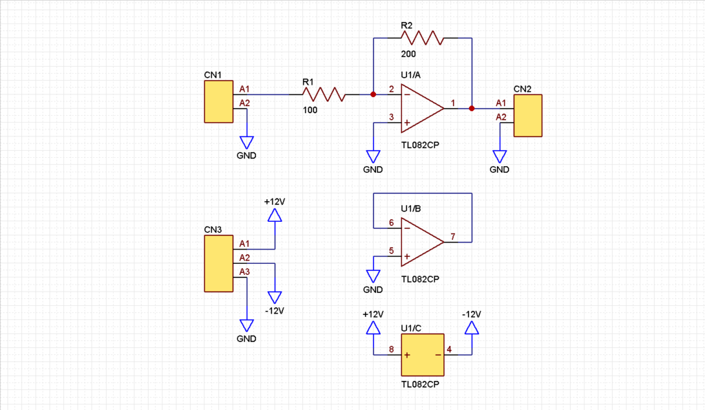
ERC (Electrical Rule Check)
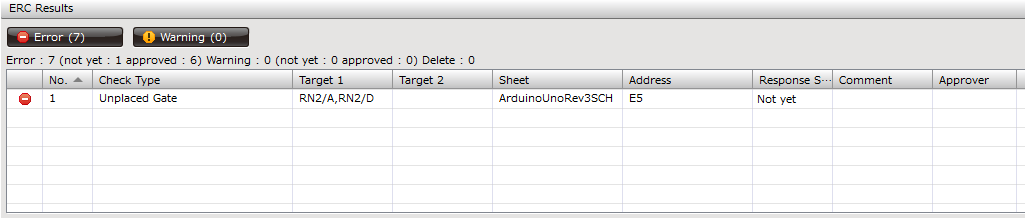
After creating a schematic, you can perform an ERC (Electrical Rule Check) to confirm that there are no electrical errors in the wiring.
If there is a wiring error, the CAD will display the result as an error or warning, allowing you to correct the mistake early in the design process.
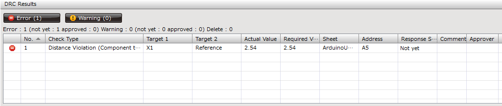
There are also circuit design CAD with DRC (Design Rule Check) functionality. It can check the layout to make the schematic easier to read.
The items to be checked for ERC/DRC can be selected at the user's discretion in the circuit design CAD settings.
Linking with Circuit Simulator
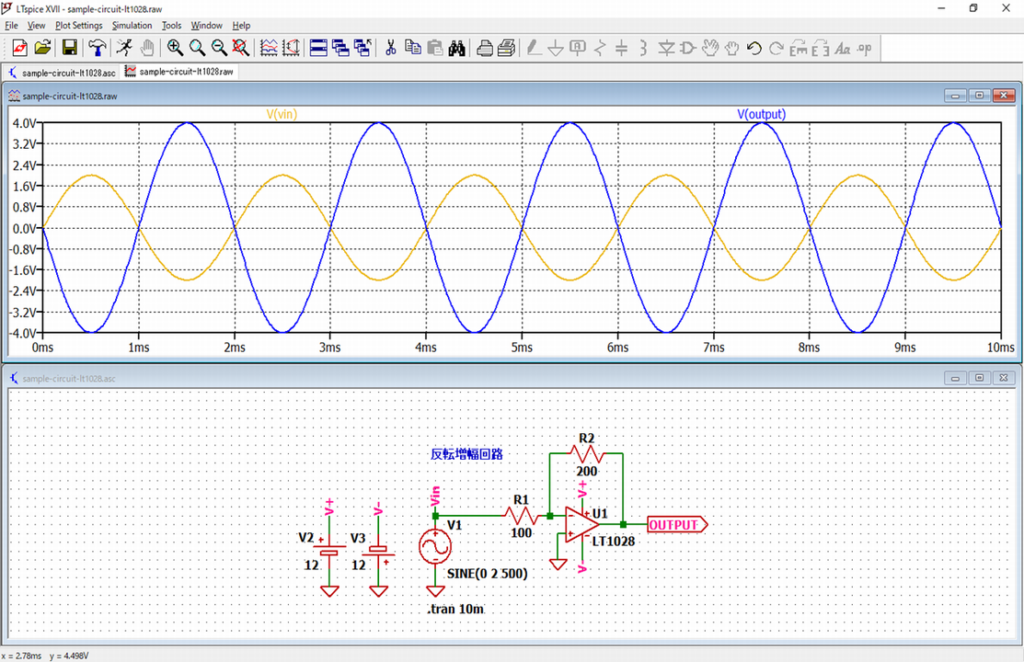
Recently, there has been an increase in the number of circuit design CADs that can be liked with circuit simulators such as LTspice, PSpice, and HSPICE.
The circuit simulation can be performed directly from the schematic created by the circuit design CAD. Therefore, there is no need to create a schematic on the circuit simulator side.
BOM (Bill of Materials) and Netlist Output
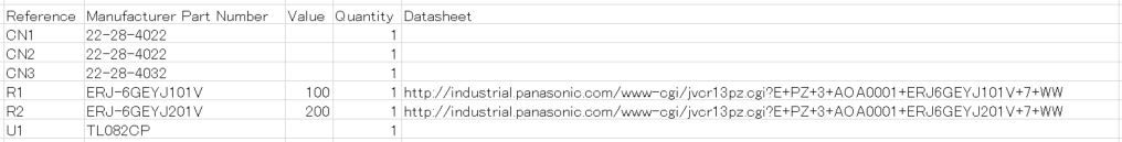
Circuit design CAD can output BOM (Bill of Material) and netlist.
BOM output can be customized, so it is easy to create company-specified BOMs.
Netlist is "the connection data between components in a schematic".
Usually, netlist output is available in a variety of third-party formats other than CAD vendors.
This allows you to deal with different CAD vendors when you outsource PCB design to your subcontractors.
In other cases, it can output a netlist for SPICE, which can be verified with circuit simulators such as LTspice, PSpice, and HSPICE.
Features of PCB Design CAD
PCB design CAD is software for pattern work by placing components on a PCB on data.
The created PCB layout data is used for PCB manufacturing and mounting. Usually, this is done by a PCB manufacturer.
The main features of PCB design CAD are as follows.
- Improving the Efficiency of PCB Layout
- Linking with Auto Routing Tool
- DRC/MRC
- 3D Functions
- Gerber Data Output
- Linking with Analysis Software
etc.
Improving the Efficiency of PCB Layout
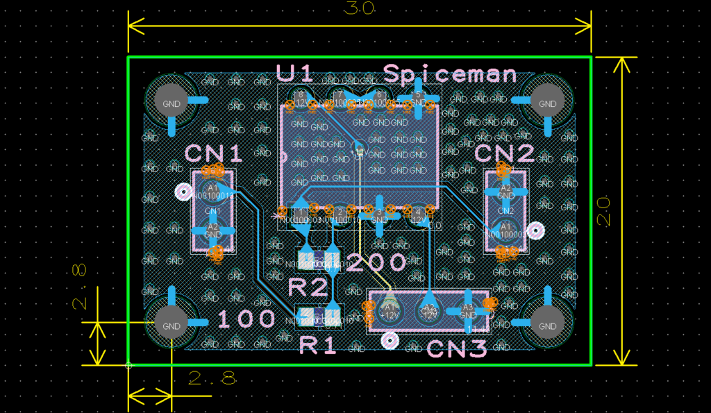
PCB design CAD can be used to improve the efficiency of PCB layout.
Rather, PCB design CAD is essential in PCB design because it is almost impossible to deal with multilayer boards by hand.
If the vendor is the same, you can have the circuit design CAD output data to the PCB design CAD for layout of the PCB.
Since the connection status is known, there is no wiring error in pattern work. It is also easy to modify and change the pattern work.
You can also handle schematics from other vendors as long as the netlist data is available.
Linking with Auto Routing Tool
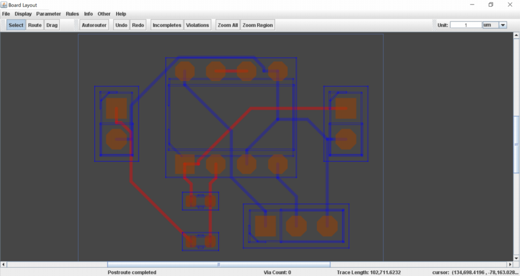
For circuits that require many wiring points, such as CPUs and FPGAs, you can save time by linking an auto routing tool.
However, it does not take electrical characteristics into account, so power supply lines, analog lines, etc. must be wired manually in advance.
DRC/MRC
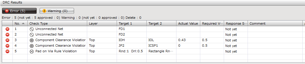
DRC (Design Rule Check) can be performed to check for violations of design rules for wiring, vias, etc.
Generally, DRC is performed after board layout is completed, but some PCB design CAD perform DRC in real time, allowing for error-free wiring work.
There are also PCB design CAD with MRC (Manufacturing Rule Check) functionality, which can be used to check for violations of manufacturing rules such as clearance between components and silk lettering angles.
The items to be checked for DRC/MRC can be selected at the user's discretion in the circuit design CAD settings.
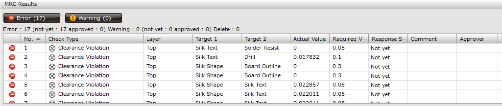
3D Functions
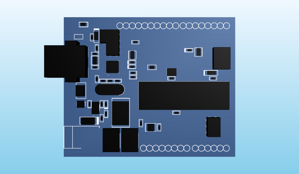
You can use the 3D viewer to view the designed PCB and check if the components are placed on the PCB as you imagined.
It can also be linked to a mechanical CAD to check the interference of PCBs and components in the case and to take thermal analysis.
Gerber Data Output
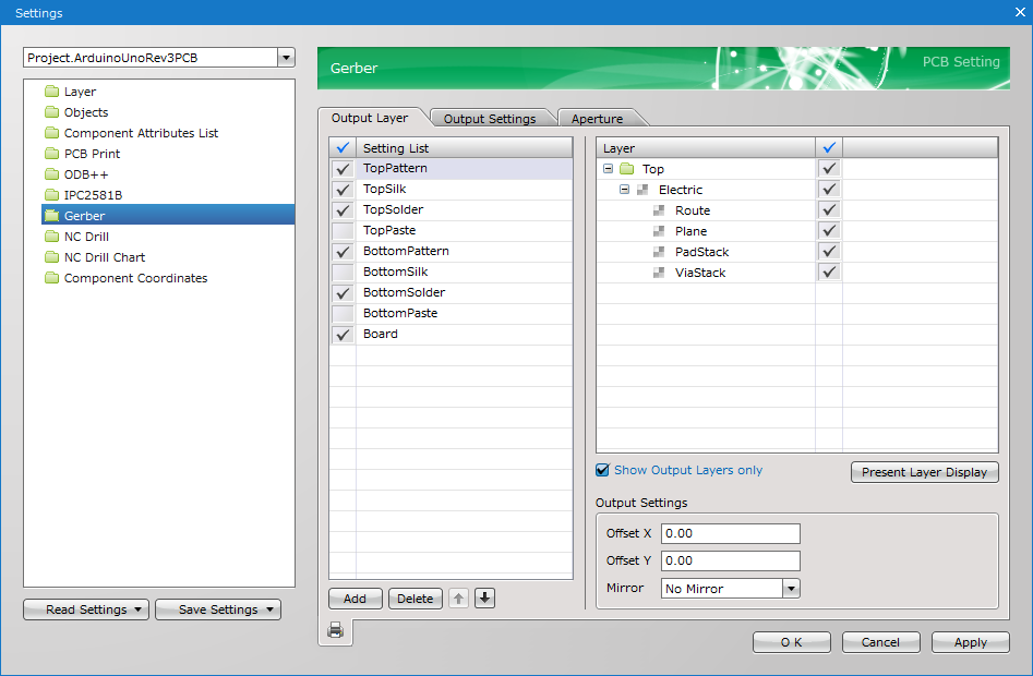
PCB design CAD can output gerber data (manufacturing files and drill files) for PCB manufacturing.
The "Gerber format" is almost a standard format in the PCB industry.
Linking with Analysis Software
PCB design CAD can be linked to analysis software such as SI/PI analysis and EMC to perform various simulations before PCB manufacturing.
Nowadays, electronic products are required to have lower voltage, higher signal speed, smaller size, and more functions, so these analyses are becoming more and more important.
How to Select Circuit Design CAD/PCB Design CAD
The following is a summary of important points to consider when selecting a Circuit Design CAD/PCB Design CAD.
Note that open-source CAD is inferior in terms of support, so it is basically recommended to choose from paid CAD.
Also, please refer to "Comparison of Circuit Design CAD/PCB Design CAD" for a detailed comparison of the differences between each CAD.
- Cost Performance
- Usability/Product Performance
- Support
Cost Performance
When introducing a Circuit Design CAD/PCB Design CAD, aren't you concerned about the "price"?
However, it is very important to consider "cost performance" rather than simply choosing free CAD.
For example, if the labor cost is \$50/hour and the price of CAD is \$1,000/month, it is worth implementing if it can save more than 20 hours/month of work compared to free CAD.
- Price of CAD: \$1,000/month
- Labor Costs: \$50/h
- Break-Even Point:\$1,000÷\$50=20 hours/month
Therefore, it is necessary to select a CAD system that strikes a balance between "Usability/Product Performance" and "price".
Usability/Product Performance
Naturally, the Circuit Design CAD/PCB Design CAD to be introduced must have the performance required for design work?
Paid CAD meets the basic specifications and offers various functions such as parts library, auto routing, 3D functions, and linking with circuit simulators and various analysis software.
"Creating component data for schematic symbols and footprints" is a particularly time-consuming task, so having a component library available can significantly reduce design time.
However, the higher the performance, the higher the CAD price tends to be, so be careful not to purchase CAD that is over-specified beyond their design level in terms of cost-effectiveness.
In addition, since these Circuit Design CAD/PCB Design CAD are designed for professionals, they tend to be packed with too many functions, making settings and operations more complicated. A good UI/UX is also important.
Recently, by linking an online electronic component company with a parts information database, some CADs can check the inventory and prices of parts used in circuits.
Basically, all paid CAD offer a free trial edition, so it is a good idea to actually use and compare them when selecting a CAD.
Support
Paid Circuit Design CAD/PCB Design CAD are well supported.
Recently, in addition to telephone and e-mail, some companies have also established Internet-based support systems, such as webinars, online manuals, and forums, which are becoming more convenient.
Even if some problems occur in the operation of the CAD, the company that sells the paid CAD is basically quicker to respond.
Free CAD, on the other hand, is basically unsupported because it is funded by the authors' volunteer spirit and donations.
If a freeze or file crash occurs, it is the user's own responsibility, and we do not know when stable version will be released.
Also, some people say that well-known free CAD is explained a lot in books and websites, but in reality, many people do not know how to use it only from those explanations.
It is a fatal disadvantage in the job to have design work stalled for days, so it is better to choose from a paid CAD system with a good support system.
Comparison of Circuit Design CAD/PCB Design CAD
Here is a list of recommended circuit design CAD and PCB design CAD.
In some cases, a free trial edition is available, so you should definitely try it out for yourself.
TOP3
| Ranking | No1 | No2 | No3 |
|---|---|---|---|
| Circuit Design CAD | Quadcept Circuit Designer | Altium Designer | KiCad Schematic Editor |
| PCB Design CAD | Quadcept PCB Designer | " | KiCad PCB Editor |
| Price of Circuit Design CAD | \$39/month (\$429/year) | \$325/month (\$3,850/year) +License Type Cost | Free |
| Price of PCB Design CAD | \$99/month (\$1,089/year) | " | Free |
| Other Purchase and Discount | Volume Discount Continuity Discount | Altium Designer SE Perpetual License | N/A |
| Free Trial Edition | AVAILABLE Non-Commercial Only Limited to 4 layers and 100 pads *1 | AVAILABLE Free for 15 days | N/A |
| Commercial Use | AVAILABLE | AVAILABLE | AVAILABLE |
| English Support | EXCELLENT Online Manual Forum Phone etc. | EXCELLENT Online Manual Forum Chat etc. | POOR |
| OS | EXCELLENT Windows 8.1 Windows 10 Windows 11 | EXCELLENT Windows 8.1 Windows 10 etc. | EXCELLENT Windows 8.1 Windows 10 Windows 11 etc. |
| License Authentication Method | EXCELLENT Network Standalone | EXCELLENT On-Demand Private Server Standalone | N/A |
| License Sharing | EXCELLENT | EXCELLENT | N/A |
| Parts Database | EXCELLENT Linking with online electronic component companies | POOR | POOR |
| Parts Library | EXCELLENT Share(About 250k parts) etc. | EXCELLENT File-based Libraries Altium Content Vault | POOR |
| Circuit Simulator | EXCELLENT Linking with LTspice | EXCELLENT Altium SPICE simulator | EXCELLENT Ngspice |
| Auto Routing | EXCELLENT Linking with Auto Routing tools | EXCELLENT Altium Auto Route | EXCELLENT Linking with Freerouting |
| 3D Functions | EXCELLENT Linking with 3D CADs | EXCELLENT Linking with 3D CADs | EXCELLENT Linking with 3D CADs |
| Data Conversion | EXCELLENT Schematic Data PCB Data | EXCELLENT Schematic Data PCB Data | GOOD EAGLE Project |
| SI/PI Analysis | GOOD SI/PI Cloud Simulation Service | GOOD Altium SI simulator (No PI Analysis) | POOR |
| EMC | GOOD Linking with DEMITASNX | GOOD Linking with EMC tools | POOR |
| Vendor | Quadcept Inc. | Altium Ltd. | CERN *Development Support |
| Head Office | Japan | USA | Switzerland |
| Main Features | Can be used anywhere in the cloud Simple and Inexpensive Subscription | Simple Subscription | Open Source Software |
| Official Web Site |
| » Official Web Site | » Official Web Site |
*1: "Quadcept Community" is limited to non-commercial, 4 layers, 1000 pads.
Others
| Ranking | Out of Ranking | Out of Ranking | Out of Ranking | Out of Ranking | Out of Ranking | Out of Ranking | Out of Ranking | Out of Ranking | Out of Ranking |
|---|---|---|---|---|---|---|---|---|---|
| Circuit Design CAD | EAGLE Premium (Fusion 360) | OrCAD Capture | CR-8000 Design Gateway | PADS Standard | Designspark PCB Pro | EasyEDA | CircuitMaker | Upverter | Fritzing |
| PCB Design CAD | " | OrCAD PCB Designer | CR-8000 Design Force | " | " | " | " | " | " |
| Price of Circuit Design CAD | \$60/month (\$495/year) | Perpetual License Cost +Maintenance Cost/year | UNCLEAR | Perpetual License Cost +Maintenance Cost/year | \$449/year | $9.9/month: Enterprise | N/A | N/A | € 8~ *Donation |
| Price of PCB Design CAD | " | Perpetual License Cost +Maintenance Cost/year | 9.8 million yen +Maintenance Cost/year | Perpetual License Cost +Maintenance Cost/year | “ | " | N/A | N/A | " |
| Other Purchase and Discount | Paid every 3 years | 1 Year License | N/A | Standard Plus Professional | N/A | N/A | N/A | N/A | N/A |
| Free Trial Edition | AVAILABLE | AVAILABLE | N/A | AVAILABLE | AVAILABLE | AVAILABLE Standard/Professional Edition Advertisements | N/A | N/A | N/A |
| Commercial Use | AVAILABLE | AVAILABLE | AVAILABLE | AVAILABLE | AVAILABLE | AVAILABLE | AVAILABLE | UNCLEAR | UNCLEAR |
| English Support | GOOD | GOOD | GOOD | GOOD | GOOD | EXCELLENT Online Manual Forum | EXCELLENT Online Manual Forum etc. | EXCELLENT Online Manual Forum etc. | POOR |
| OS | Windows 8.1 Windows 10 etc. | Windows 8.1 Windows 10 Windows 11 etc. | Windows 8.1 Windows 10 etc. | UNCLEAR | Windows 10 | EXCELLENT WEB Browser Windows 8.1 Windows 10 etc. | EXCELLENT Windows 10 Windows 11 | GOOD WEB Browser | Windows 8.1 Windows 10 Windows 11 etc. |
| License Authentication Method | License Key | USB Dongle Network Address | UNCLEAR | Mobile Compute Node-Locked Float | Account Registration | N/A | N/A | N/A | N/A |
| License Sharing | UNCLEAR | GOOD | UNCLEAR | UNCLEAR | N/A | N/A | N/A | N/A | N/A |
| Parts Database | POOR | POOR | POOR | POOR | POOR | GOOD Linking with LCSC | POOR | GOOD | POOR |
| Parts Library | GOOD | POOR | EXCELLENT | EXCELLENT | EXCELLENT | EXCELLENT | EXCELLENT | EXCELLENT | GOOD |
| Circuit Simulator | EXCELLENT | POOR | EXCELLENT | GOOD | EXCELLENT | EXCELLENT | POOR | POOR | POOR |
| Auto Routing | EXCELLENT | POOR | EXCELLENT | EXCELLENT | EXCELLENT | EXCELLENT | EXCELLENT | EXCELLENT | POOR |
| 3D Functions | EXCELLENT | EXCELLENT | EXCELLENT | EXCELLENT | EXCELLENT | EXCELLENT | EXCELLENT | EXCELLENT | GOOD |
| Data Conversion | POOR | POOR | POOR | EXCELLENT | POOR | EXCELLENT Altum/EAGLE/KiCad etc. | EXCELLENT Altum/KiCad/OrCad etc. | POOR | POOR |
| SI/PI Analysis | POOR | POOR | EXCELLENT | GOOD | POOR | POOR | POOR | POOR | POOR |
| EMC | POOR | POOR | EXCELLENT | GOOD | POOR | POOR | POOR | POOR | POOR |
| Vendor | Autodesk, Inc. | Cadence Design Systems, Inc. | ZUKEN Inc. | Siemens Industry Software Inc. | RS Group plc | LCSC Electronics Technology Co., Ltd. | Altium Ltd. | Altium Ltd. | Interaction Design Lab Potsdam |
| Head Office | USA | USA | Japan | USA | UK | China | USA | USA | Germany |
| Main Features | Linking with Mechanical CAD | Used in over 85 countries | Largest company in Japan | Formerly known as "Mentor Graphics Corp." | Linking with RS | Supported by LCSC | Same engine as Altium Designer | Easy drag & drop design | Open Source Software |
| Official Web Site | » Official Web Site | » Official Web Site | » Official Web Site | » Official Web Site | » Official Web Site | » Official Web Site | » Official Web Site | » Official Web Site | » Official Web Site |
Circuit Design CAD/PCB Design CAD Ranking
Here is a ranking of circuit design CAD and PCB design CAD.
No1
 Quadcept
- Circuit Design CAD: Quadcept Circuit Designer
- PCB Design CAD: Quadcept PCB Designer
- The world's cloud-based electronic CAD system that can be used anywhere
- Simple and inexpensive subscriptions from $39/month
- Short learning time for CAD with careful support system
- About 250,000 free parts data to reduce design time
- Data conversion makes it easy to switch from another company's CAD
- Software installation required
- Training is charged(Free online manuals and free online seminars available)
![]() Quadcept is the world's first cloud-based circuit/board design CAD system, so you can use it at work, at home, on business trips overseas, or anywhere else you have an Internet connection.
Quadcept is the world's first cloud-based circuit/board design CAD system, so you can use it at work, at home, on business trips overseas, or anywhere else you have an Internet connection.
It offers a subscription service with no initial or maintenance fees. Circuit design CAD is available for \$39 and up, and PCB design CAD for \$99 and up.
In addition, there are many other attractive points for users, such as the short learning time of CAD through the support system and the reduction of design time through the 250,000 parts data.
However, Quadcept is just a software that is installed on a local PC, with the infrastructure of "license activation", "parts library", and "parts inventory and price database" in the cloud for business efficiency.
Therefore, you need to make sure that the PC you will use Quadcept on meets the system requirements, including the supported OS, in advance.
Free online manuals and free online seminars are available, but there is cost for training. If you need customized training for your company, you may want to consider it.
\ Over 72,000 users! Also used by TOYOTA! /

See detailed specifications
| Specifications | Quadcept Professional |
|---|---|
| Circuit Design CAD | Quadcept Circuit Designer |
| PCB Design CAD | Quadcept PCB Designer |
| Price of Circuit Design CAD | \$39/month (\$429/year) |
| Price of PCB Design CAD | \$99/month (\$1,089/year) |
| Other Purchase and Discount | Volume Discount: 5 to 10 pcs 5%OFF 11 to 20 pcs 7%OFF 21 to 30 pcs 10%OFF After 31 pcs 12%OFF Continuity Discount: 2nd year 5%OFF 3rd year 7%OFF 4th year 10%OFF After 5th year 12%OFF |
| Free Trial Edition | Quadcept Professional(No License): Non-commercial only Limited to 4 layers and 100 pads *More than 4 layers and 100 pads can be used as a Viewer. *The full-featured free trial edition is valid for two weeks (contact us). Quadcept Community: Non-commercial only Limited to 4 layers and 1000 pads |
| Commercial Use | Available for commercial use(License Required) |
| English Support | Online Manual Videos Forum WEB Seminar Phone Paid Training *Email and phone support is available after license purchase. |
| OS | Windows 8.1 Windows 10 (1507~2004) Windows 11 *32bit/64bit |
| License Authentication Method | Network: Obtain and activate a license from Quadcept's license server via the Internet. Standalone: Activate a license offline by capturing it in advance on the device. |
| License Sharing | License sharing available |
| Parts Database | Digi-Key Mouser RS Components Chip One Stop CoreStaff |
| Parts Library | Share(Free parts library): About 250k parts data are available for free. Digi-Key Mouser RS Components Chip One Stop CoreStaff ROHM OMRON TOKIN/KEMET Murata etc. Tie-up with parts data library provider: Ultra Librarian/About 2,000k parts data are available for free. SamacSys/About 1,500k parts data are available for free. *Part data is duplicated. |
| Circuit Simulator | Linking with "LTspice". |
| Auto Routing | Linking with other auto routing tools. *Output of DSN files is possible. *Input of RTE files is possible. |
| 3D Functions | 3D viewer function Linking with other 3D CADs. *Input/output of 3D data is possible. *"Collision Detection" and "Thermal Analysis" can be checked in advance. |
| Data Conversion | CAD for schematic data conversion: CR5000 SD OrCad Capture Altium/Protel CAD for PCB data conversion: Allegro OrCAD Layout Board Station Expedition PADS power PCB ODB++ CADSTAR CR5000 BD CR5000 PWS CADVANCE Altium/Protel EAGLE IPC-2581 *Read in ALTAIR's PDB ASCII file. *CR5000 BD can also be converted in Quadcept. |
| SI/PI Analysis | Estimate on a case-by-case basis |
| EMC | Linking with the EMI noise suppression software "DEMITASNX". JPY110,000/Analysis Report |
| Vendor | Quadcept Inc. |
| Head Office | USA |
No2 Altium Designer

- Circuit Design CAD: Altium Designer/Altium Designer SE
- PCB Design CAD: Altium Designer
- High-end class CAD
- Used all over the world, especially in the United States and Europe.
- High cost of using CAD
- Training is charged
Altium Designer is a high-end circuit design CAD/PCB design CAD that is used all over the world, especially in the US and Europe.
It is relatively expensive at $325/month, but the fee structure is easy to understand, mainly based on subscription services.
Perpetual license ($3,850/year) is also available, which is more economical if you plan to use it for more than 3 years.
There is also a circuit design CAD-only edition, "Altium Designer SE", and a 15-day free evaluation edition.
However, there is a cost for changing the license activation, and it is not possible to purchase PCB design CAD alone, which is not user-friendly.
See detailed specifications
| Specifications | Altium |
|---|---|
| Circuit Design CAD | Altium Designer |
| PCB Design CAD | " |
| Price of Circuit Design CAD | \$325/month (\$3,850/year) License Type Cost On-Demand: +\$0/year Private Server: +\$500/year Standalone: +\$500/year Single Site (Domestic only): +\$0/year Continental (Specific continent only): +\$1,925/year Global: +\$3,850/year |
| Price of PCB Design CAD | " |
| Other Purchase and Discount | Altium Designer SE (Schematic Basic Set) Perpetual License |
| Free Trial Edition | Same features as the full edition Available for free (15 days) |
| Commercial Use | Available for commercial use |
| English Support | Online Manual Chat Videos Forum Paid Training etc. |
| OS | Windows 7 SP1 Windows 8.1 Windows 10 *64bit only |
| License Authentication Method | On-Demand (Network): Obtain and activate a license from Altium's license server via the Internet. Private Server: Obtain and activate a license from a license server installed in the company. Standalone: Activate a license offline by capturing it in advance on the device. |
| License Sharing | License sharing available |
| Parts Databse | POOR |
| Parts Library | File-based Libraries: Parts library can be downloaded and used Altium Content Vault: "Manufacturer Part Search" enables the use of parts library in the cloud. |
| Circuit Simulator | Altium SPICE simulator *Supports SPICE models from LTspice, Pspice, etc. |
| Auto Routing | Altium Auto Route |
| 3D Functions | 3D viewer function Linking with other 3D CADs. *Input/output of 3D data is possible. *"Collision Detection" and "Thermal Analysis" can be checked in advance. |
| Data Conversion | Cadstar EAGLE Allegro PADS DxDesigner OrCAD Protel 99 SE CR-5000 etc. |
| SI/PI Analysis | Altium SI simulator Linking with other PI simulators |
| EMC | Linkinged with other EMC analysis tools. |
| Vendor | Altium Ltd. |
| Head Office | Japan |
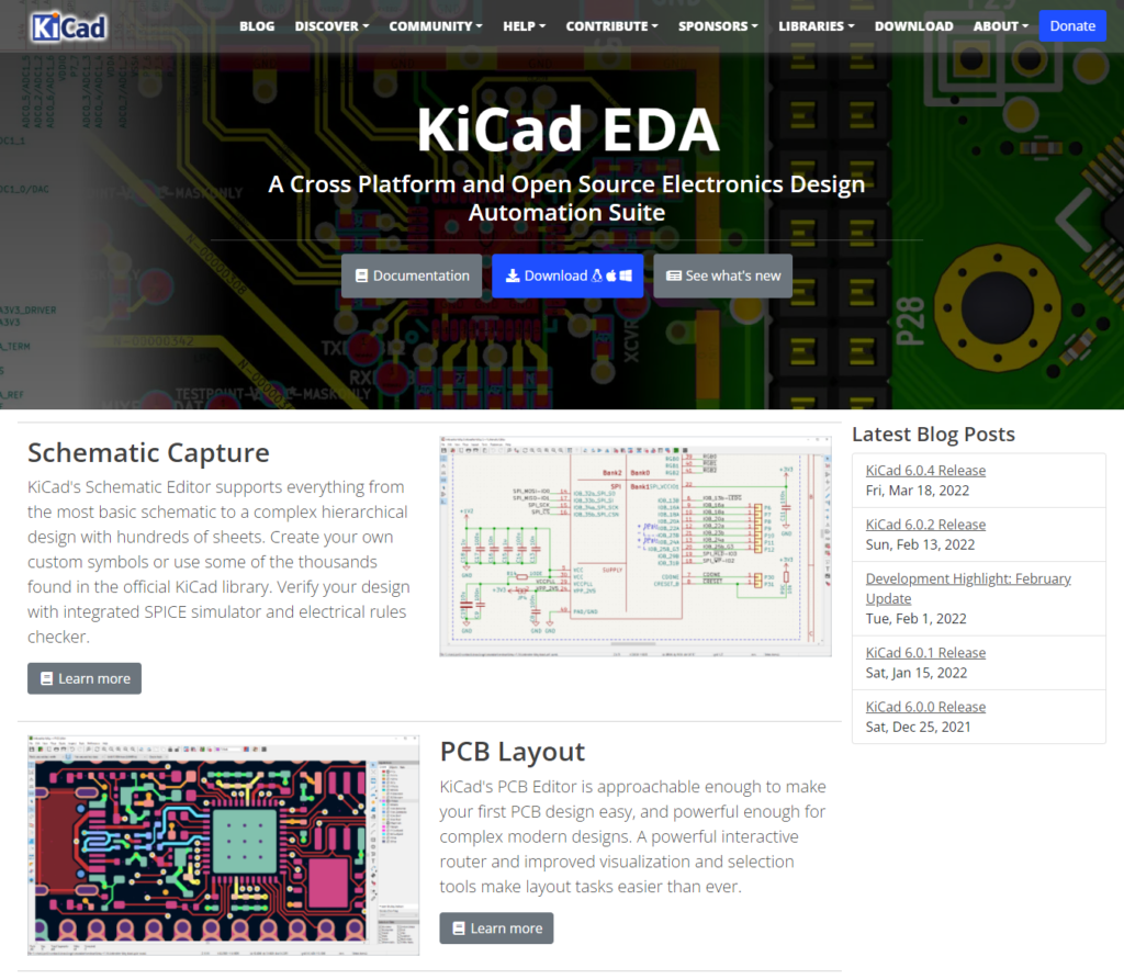
No3 KiCad
- Circuit Design CAD: KiCad Schematic Editor
- PCB Design CAD: KiCad PCB Editor
- Free to use
- Professional level of CAD functionality
- No support for open source software
- Not linked to analysis software such as SI/PI analysis and EMC
KiCad is a circuit design/PCB design CAD of open source software, so anyone can use it for free.
What's more, since CERN started supporting its development in 2013, it has come closer to professional-level CAD.
However, since it is only an open source software CAD, there is no support, so it may take some time to solve the problem.
In addition, these simulations cannot be performed prior to PCB manufacturing because they are not linked to analysis software such as SI/PI analysis and EMC.
See detailed specifications
| Specifications | KiCad |
|---|---|
| Circuit Design CAD | KiCad Schematic Editor |
| PCB Design CAD | KiCad PCB Editor |
| Price of Circuit Design CAD | Free |
| Price of PCB Design CAD | Free |
| Other Purchase and Discount | N/A |
| Free Trial Edition | N/A |
| Commercial Use | Available for commercial use |
| English Support | No support |
| OS | Windows 8.1 Windows 10 Windows 11 *32bit/64bit Support for macOS, Linux, FreeBSD, etc. |
| License Authentication Method | N/A |
| License Sharing | N/A |
| Parts Database | POOR |
| Parts Library | POOR |
| Circuit Simulator | Ngspice Compatible with SPICE models of SPICE, LTspice, PSpice, and HSPICE. |
| Auto Routing | Linking with "Freerouting". |
| 3D Functions | 3D viewer function Linking with other 3D CADs. *Input/output of 3D data is possible. *"Collision Detection" and "Thermal Analysis" can be checked in advance. |
| Data Conversion | EAGLE projects can be imported. |
| SI/PI Analysis | POOR |
| EMC | POOR |
| Vendor | CERN *Development Support |
| Head Office | Switzerland |
Other Circuit Design CAD/PCB Design CAD
For your reference, here are some circuit design CADs and PCB design CADs that are not ranked.
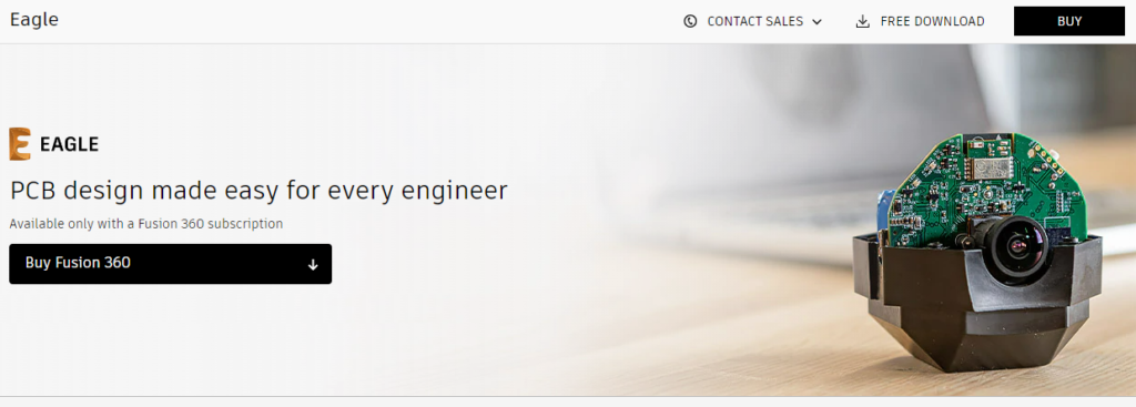
EAGL Premium(Fusion 360)
- Circuit Design CAD: EAGLE Premium(Fusion 360)
- PCB Design CAD: EAGLE Premium(Fusion 360)
- Easy to obtain parts libraries
- Good at linking with mechanical design CAD
- Eagle Standard plan is gone
- Only option is Fusion360 subscription version
EAGLE Premium is a circuit design CAD/PCB design CAD that is included as a feature of Fusion360.
Autodesk, the developer and distributor of Fusion360, also offers AutoCAD and Inverntor as its main products, and EAGLE Premium has extensive functionality for integration with these mechanical design CAD (3D CAD).
Originally, EAGLE was often used as a hobby because a non-commercial free version (2 schematic sheets/2 layers/board size up to 80 cm2) was available and component libraries were relatively easy to obtain.
Also, there was an EAGLE Standard (4 layers/board size up to 160cm2) plan for commercial use.
But since EAGLE itself has been incorporated and integrated into Fusion360, the only option is now a Fusion360 subscription version (e.g. \$495/year).
OrCAD

- Circuit Design CAD: OrCAD Capture
- PCB Design CAD: OrCAD PCB Designer
- Used in over 85 countries
- Various options such as PSpice
- High initial, maintenance, and option costs
- Training is charged
OrCAD is a mid-range circuit design CAD/PCB design CAD that has been used in over 85 countries around the world.
A variety of options are available, including PSpice for circuit analysis, parts library creation service, and board analysis.
However, although it is affordable compared to high-end class CAD, the cost is high when you include the initial cost, maintenance cost, and option cost.
It is especially painful that auto routing tool and circuit simulator are treated as options.
ZUKEN CR-8000
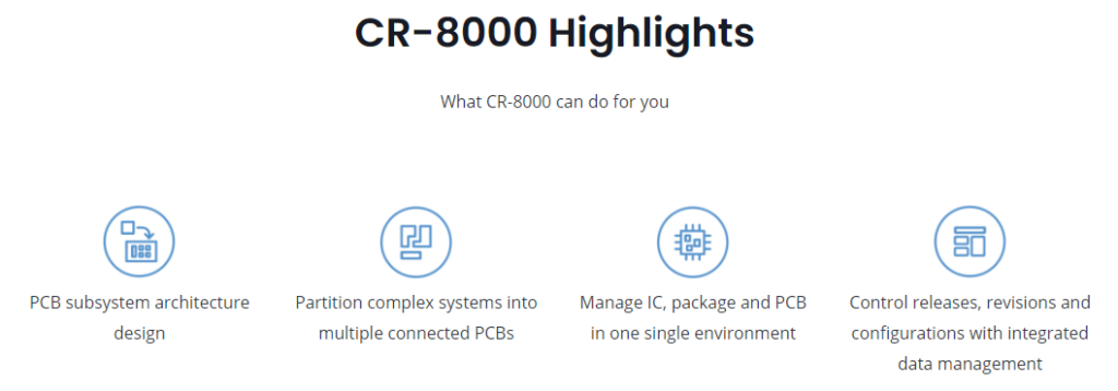
- Circuit Design CAD: CR-8000 Design Gateway
- PCB Design CAD: CR-8000 Design Force
- High-end class CAD
- Used in over 85 countries
- High initial, maintenance, and option costs
- No free trial edition
- Training is charged
The CR-8000 series is a high-end class EDA tool developed and sold by ZUKEN Inc, the largest company in Japan.
The circuit design CAD is "Design Gateway" and the PCB design CAD is "Design Force". Compared to other companies' products, the CR-8000 series offers higher performance and reduces design time.
However, it is only a high-end class CAD, and the list price of the professional edition of "Design Force" is 9.8 million yen.
Therefore, the number of companies that can install CR-8000 will be limited because of the considerable amount of money involved.
In addition, "Board Viewer" that display PCB data designed with Design Force can be downloaded free of charge, but the free trial edition of Design Gateway/Design Force does not seem to exist on the official ZUKEN WEB site.
PADS Standard

- Circuit Design CAD: PADS Standard
- PCB Design CAD: PADS Standard
- Choose from Standaard, Standaard Plus, and Professional
- Used all over the world, especially in the United States
- License activation is inconvenient
- Training is charged
PADS is a circuit design CAD/board design CAD originally developed and sold by Mentor Graphics. There are Standaard, Standaard Plus, and Professional by function.
(Currently, it has been acquired by Siemens and operates as Siemens EDA.)
The price of the CADs are not listed and you cannot download the free trial editon from the official website. If you want to know more details, you need to contact Siemens EDA.
Also, compared to network authentication via the Internet, setting up PADS license authentication is more complicated.
DesignSpark

- Circuit Design CAD: DesignSpark PCB Pro
- PCB Design CAD: DesignSpark PCB Pro
- Commercial use is possible even in the free edition
- Easy to obtain parts libraries
- UI is not excellent
- Not good support
Designspark PCB Pro is a circuit design CAD/PCB design CAD provided by "DesignSpark". it is a community platform for developers operated by RS Components.
The price is a reasonable \$449/year, and there is also a free version, DesignSpark PCB, which has no restrictions and can be used for commercial purposes.
However, because of the low cost, including the PRO edition, the UI and support are not so excellent.
EasyEDA
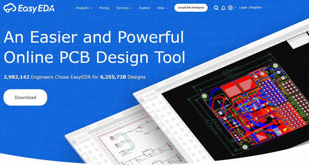
- Circuit Design CAD: EasyEDA
- PCB Design CAD: EasyEDA
- Cloud-based software that runs in a WEB browser
- Easy ordering of parts and PCBs
- Parts ordered from LCSC and PCBs ordered from JLCPCB only
- Free version has advertisements
EasyEDA is a cloud-based circuit design CAD/PCB design CAD that runs in a WEB browser.
(You can also download EasyEDA's standalone client software for Windows.)
It is provided by LCSC, a China's major electronic component supplier, and has a full range of functions for a free CAD system.
Although parts are limited to LCSC and PCBs are limited to JLCPCB, the system also includes a function that allows easy ordering of parts and PCBs.
However, the Standard(Free Forever) and Professional(Free Now) versions display advertisements.
To remove the ads, there is a plan to purchase the $9.9/month Enterprise version, which is scheduled for release in the future.
CircuitMaker
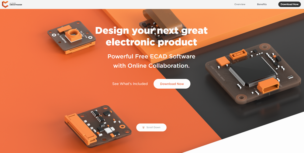
- Circuit Design CAD: CircuitMaker
- PCB Design CAD: CircuitMaker
- Same engine as Altium Designer
- Lack of extensive analysis functions
CircuitMaker is Altium's free circuit design CAD/PCB design CAD.
It is positioned between Altium Designer and Upverter, which are also offered by Altium.
CircuitMaker uses the same engine as Altium Designer to implement the schematic editor and PCB editor.
However, the circuit simulator has been removed from the current version, and the analysis functions are not extensive.
There were plans for CircuitMaker and Upverter to merge their design platforms, but the products still remain separate.
Upverter
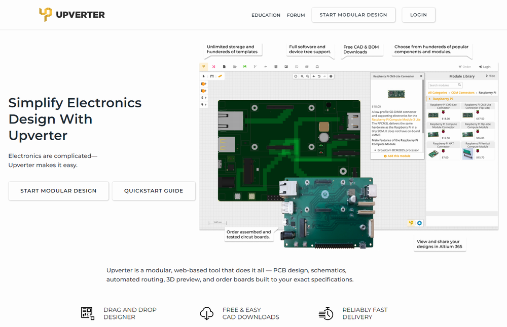
- Circuit Design CAD: Upverter
- PCB Design CAD: Upverter
- Cloud-based software that runs in a WEB browser
- Easy drag & drop design
- Easy ordering of PCBs
- Impossible to run on Windows or other OS
- Not suitable for commercial use
- PCBs ordered from gumstix only
Upverter is Altium's free circuit design CAD/PCB design CAD, which is cloud-based and runs in a web browser.
It is easy to design by dragging and dropping modules and parts.
Therefore, compared to Altium Designer and CircuitMaker, which are also offered by Altium, this software is more suitable for beginners.
There are also a wide variety of templates for PCBs that have already been designed and can be easily ordered through the PCB order function.
However, these specifications are different from those of general circuit design CAD/PCB design CAD, making it less suitable for commercial use.
There were plans for Upverter and CircuitMaker to merge their design platforms, but the products still remain separate.
Fritzing
- Circuit Design CAD: Fritzing
- PCB Design CAD: Fritzing
- Physical wiring diagrams, schematics, and board layouts are linked
- Especially easy to use for Arduino circuits
- A minimum donation of 8 euros is required
- Not suitable for commercial use
Fritzing is a unique circuit design CAD/PCB design CAD that links physical wiring diagrams of breadboard, schematics, and board layouts.
Of course, the wiring and layout drawn in conjunction is difficult to see and needs to be corrected. However, since you can select Arduino boards as components, it is easy to use for Arduino circuits.
On the other hand, due to these characteristics, it is not suitable for commercial and complex circuit/PCB design. It is better to think of it as a hobby for electronic engineering.
Please note that since version 0.9.4 of Fritzing, a minimum donation of 8 euros is now required.
Although it is not recommended, Fritzing is open source software, so you can legally download the installer from GitHub for free.