What is an Ideal Op-Amp?
This article describes the "ideal op-amp" in detail.
To understand real op-amps, it is very important to have a deep understanding of an ideal op-amp beforehand.
Why do we need to understand an ideal op-amp?
An ideal op amp is an op amp that is ideal in all its characteristics. If ideal op amps existed in the world, we could use them in any circuit.
However, an ideal op amp is only ideal and do not exist in the real world.
So why do we need to understand an ideal op amp?
One answer is that ideal op amps are "easy to understand".
Indeed, it is impossible to design a circuit with knowledge of ideal op amps alone, because the characteristics of an ideal op amp are different from those of a real op amp.
However, it is difficult for beginners to suddenly understand the characteristics of real op-amps, such as "high-precision op-amps" and "high-speed op-amps," because they have very different characteristics.
Therefore, it is smoother to learn about real op-amps after first learning about ideal op-amps whose parameters are ideal and simple.
In other words, by establishing a standard of "ideal op-amp" in your mind, you will be able to correctly understand the characteristics of the real op-amp.
Ideal Op-Amp Characteristics
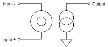
Ideal Op-Amp Schematic Symbol
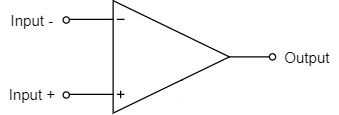
$$V_{output}=A\left(V_{input+}-V_{input-}\right)$$
$$A:Gain$$
The schematic symbol for an ideal operational amplifier is represented by three pins: Input +, Input -, and Output, as shown above.
(real op-amps are equipped with power supply pins to drive the op-amps, etc.)
The characteristics of an ideal operational amplifier are then as follows:
- Differential Gain:∞
- Common-Mode Gain:0
- Input Impedance:∞
- Outpu Impedance:0
- Bandwidth:∞
etc.
This means that even the smallest differential signal can be amplified to ∞ in all frequency bands and is not affected by the impedance of the circuit connected to the input and output terminals.
Each item is described in detail below:
Differential Gain
An ideal op amp has a gain of ∞ for differential input signals.
It is called an open-loop gain because it does not involve negative feedback.
A differential gain of ∞ means that even if a voltage of 100uV is input to Input+ and 0V to Input-, the voltage at the output will be ∞V.
Therefore, the difference between the two input pins is close to 0V, and the Input+ and Input- pins can be considered to be connected virtually inside the op amp.
It is called Virtual Short.
Even a real op-amp has an open-loop gain of 100dB or more, so if a voltage of 100uV is input to Input+ and 0V to Input-, the voltage at the output will be 10V, which is a sufficient level of voltage to output.
Therefore, the virtual short is very important in understanding the characteristics of op-amps, not only ideal op-amps but also real op-amps.
Common-Mode Gain
An ideal operational amplifier has 0 gain for common-mode input signals.
Therefore, if a signal of exactly the same voltage is input to the two input terminals, the difference will be 0, which means the gain will also be 0.
Input Impedance
The input impedance of an ideal op-amp is ∞.
It is not affected by the output impedance of the circuit connected to the input terminals of the ideal op-amp and can capture the required signal level without causing a voltage drop.
Output Impedance
The output impedance of an ideal op-amp is 0.
It is not affected by the input impedance of the circuit connected to the output terminals of the ideal op-amp, and the required signal level can be extracted without causing a voltage drop.
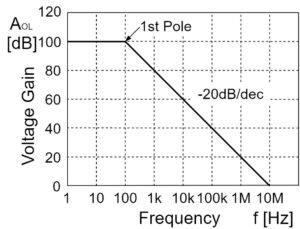
Bandwidth
The bandwidth of an ideal op-amp is ∞.
The gain of a real op-amp decreases with each increase in frequency, but the gain of an ideal op-amp does not decrease at higher frequencies.
The GB product (gain bandwidth width product) is also ∞, since both the open-loop gain and bandwidth are ∞.
Nullor Model
The nullor model is a kind of virtual element that can be used to represent a model of an ideal op-amp.
Nullator
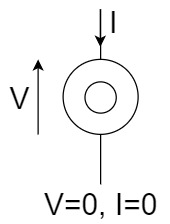
The nullator is a virtual element that is "0" (V=0, I=0) for both voltage and current.
Norator
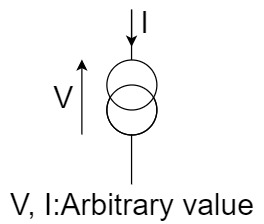
A norator is a virtual element whose voltage and current can be "arbitrary values" determined by the peripheral circuits.
Short(Nullor Model)
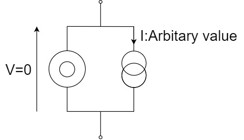
By connecting a nullator and a norator in parallel, a "short" can be represented.
Open(Nullor Model)
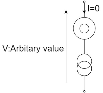
By connecting a nullator and a norator in series, an "open" can be represented.
Ideal Op-Amp(Nullor Model)
Since the two input terminals of an ideal op-amp are completely virtual shorts (V=0, I=0), the inputs can be represented by a narrator.
And the output terminals of an ideal op-amp amplify voltage and current at arbitrary values (V, I: arbitrary) for differential inputs, so the outputs can be represented by a norator.
Op-Amp Typical Circuits
In this section, Op-Amp typical circuits are described using the nullor model.
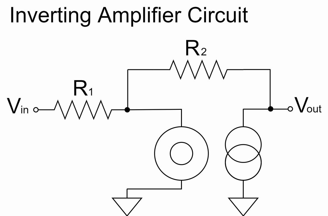
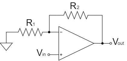
Inverting Amplifier Circuit
Inverting Amplifier Circuit
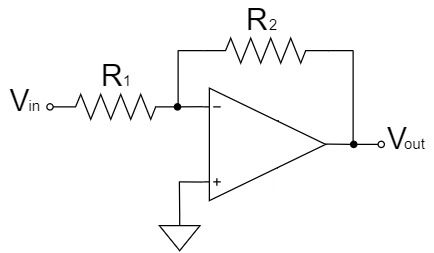
$$V_{out}=-\frac{R_2}{R_1}V_{in}$$
As shown in the equation above, the inverting amplifier circuit amplifies $V_{in}$ by a factor of $\frac{R_2}{R_1}$ and outputs it to $V_{out}$.
Also, the $V_{out}$ signal is inverted, as indicated by the "$-$" polarity.
For example, if $R_1=1kΩ, R_2=10kΩ, V_{in}=1V$;
$$V_{out}=-\frac{10k}{1k} \times 1=-10[V]$$
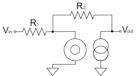
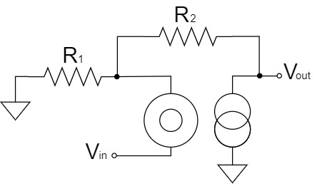
To obtain this equation, we replace the ideal op-amp with the nullor model and calculate the inverting amplifier circuit as shown below:
Inverting Amplifier Circuit(Nullor Model)
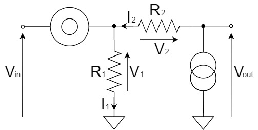
We will try to change the above schematic for clarity.
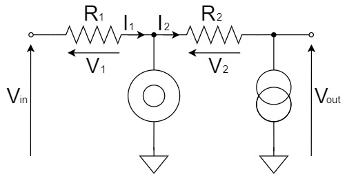
$$I_1=\frac{V_1}{R_1}=\frac{V_{in}}{R_1}$$
$$I_2=I_1$$
$$V_2=R_2I_2=\frac{R_2}{R_1}V_{in}$$
$$V_{out}=-V_2=-\frac{R_2}{R_1}V_{in}$$
Thus, from the equivalent circuit of inverting amplification using the nullor model, we were able to derive the equation.
Non-inverting Amplifier Circuit
Non-inverting Amplifier Circuit
$$V_{out}=\left(1+\frac{R_2}{R_1}\right)V_{in}$$
As shown in the equation above, the non-inverting amplifier circuit amplifies $V_{in}$ by a factor of $1+\frac{R_2}{R_1}$ and outputs it to $V_{out}$.
For example, if $R_1=1kΩ, R_2=10kΩ, V_{in}=1V$;
$$V_{out}=\left(1+\frac{10k}{1k}\right) \times 1=11[V]$$
To obtain this equation, we replace the ideal op-amp with the nullor model and calculate the non-inverting amplifier circuit as shown below:
Non-inverting Amplifier Circuit(Nullor Model)
We will try to change the above schematic for clarity.
$$I_1=\frac{V_1}{R_1}=\frac{V_{in}}{R_1}$$
$$I_2=I_1$$
$$V_2=R_2I_2=\frac{R_2}{R_1}V_{in}$$
$$V_{out}=V_{in}+V_2=V_{in}+\frac{R_2}{R_1}V_{in}=\left(1+\frac{R_2}{R_1}\right)V_{in}$$
Thus, from the equivalent circuit of non-inverting amplification using the nullor model, we were able to derive the equation.
Can circuit design be done with ideal op-amps?
As explained at the beginning of this article, an ideal op amps is only ideal that is not existed in the real world.
To design circuits using op-amps, it is necessary to understand the characteristics of real op-amps, building on the knowledge of an ideal op-amp that you have learned so far.
For example, an ideal op-amp can amplify to ∞ with differential amplification, but a real op-amp can only amplify up to the range of the supply voltage driving the op-amp.
In addition, each op-amp has different parameter characteristics for the real op-amp, as shown below, and it is necessary to select the best op-amp for the circuit to be designed.
- General Purpose Op-Amp: All characteristics are average.
- High Precision Op-Amp: DC characteristics are good but AC characteristics are bad.
- High Speed Op-Amp: AC characteristics are good but DC characteristics are bad.
etc.
To understand these real op-amps, you must be able to understand the specifications (specs) of each op amp.
For a detailed explanation of absolute maximum ratings and electrical specifications of op-amps, please refer to the following article.