.nodealias : LTspice -- Short Circuit between Nodes
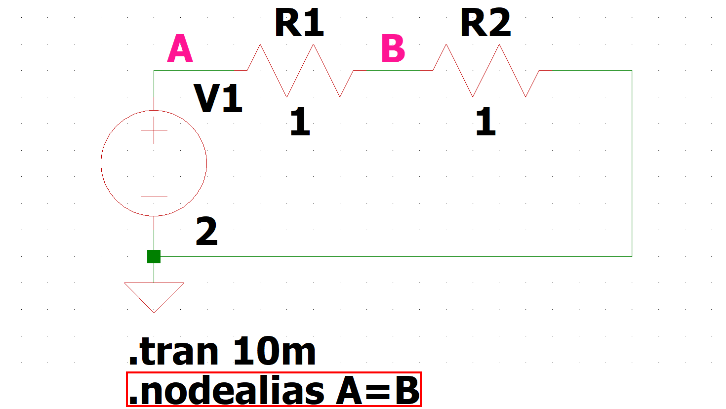
This article details the use of the dot command ".nodealias".
.nodealias" can be used to short between nodes without making wire connections on the schematic.
".nodealias" syntax
The ".nodealias" syntax is as follows. It allows shorting between nodes without making wire connections on the schematic.
- No need to change schematics
- Easily undo ".nodealias" by deleting the command line or commenting out
Because of the characteristics listed above, it can be used to temporarily modify schematics for large and complex schematics, for example, when considering design changes.
As an example, node "A" and node "B" are connected as follows:
.nodealias A=BExamples of ".nodealias" simulation
As an example of ".nodealias" simulation, we would like to check the voltage values when node "A" and node "B" are shorted in a circuit with a power supply and a resistor connected in series.
In addition, if you have never created a schematic in LTspice, please refer to the following article.
We have also prepared a pre-made schematic here, which you can download by clicking on the link below if you would like to start the simulation immediately.
Create a schematic with the power supply and resistors connected in series as shown below.
Also, set the voltage value to 2[V], the resistance value to 1[Ω] each, and the transient analysis to 10[ms].
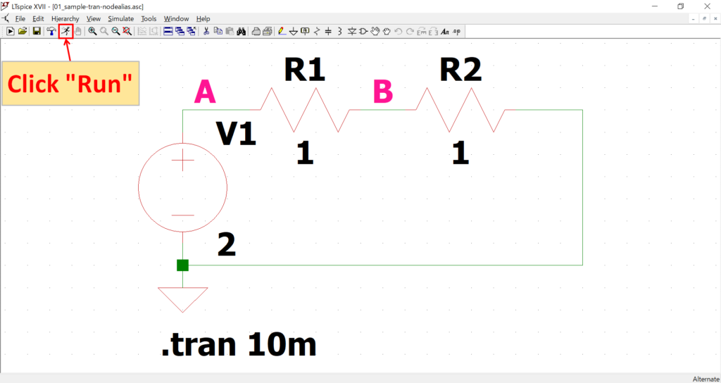
First, check the voltage value of node "B" before using ".nodealias".
Click "Run" on the toolbar to run the simulation.
For a detailed explanation of transient analysis (.tran), please refer to the following article.
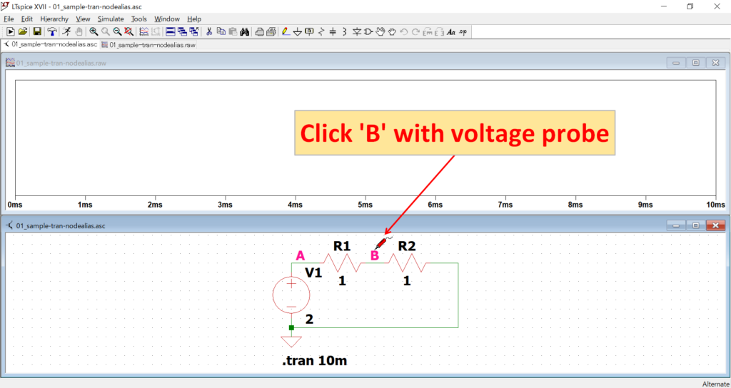
Move the mouse cursor to node "B" to switch to the voltage probe and click on it.

The voltage value of node "B" is 1[V] because 2[V] of the supply voltage is divided by 1/2 by resistors "R1" and "R2".
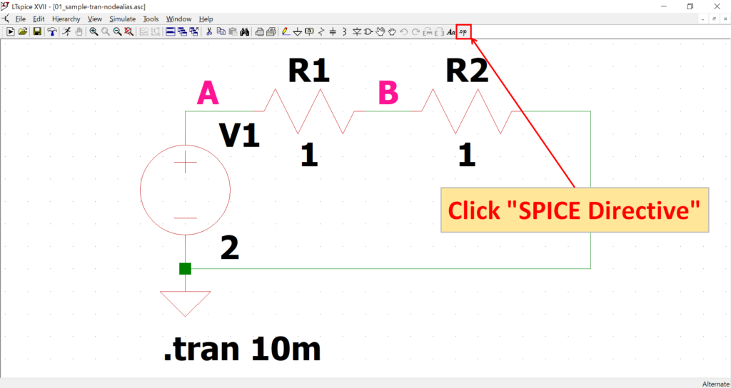
Next, click on "SPICE Directive" in the toolbar to create the ".nodealias" syntax.
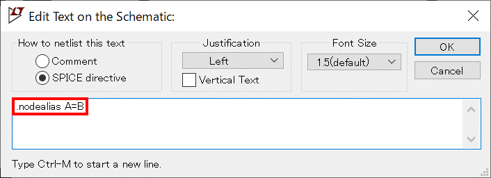
The ".nodealias" syntax is described and deployed as follows
.nodealias A=BThis time, we will connect nodes "A" and "B" and short them.
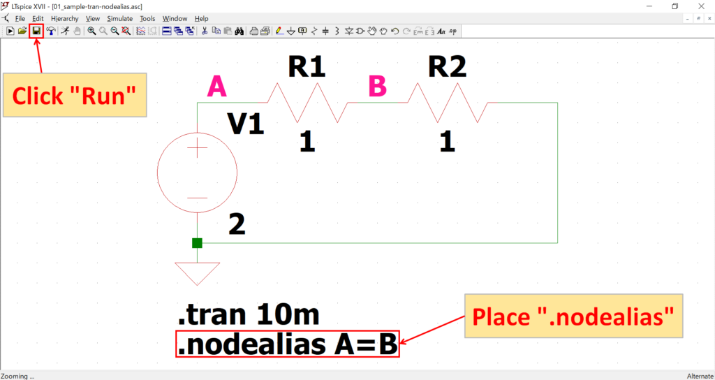
After placing the ".nodealias" syntax, click "Run" on the toolbar.
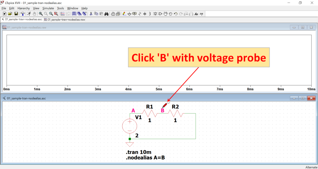
Move the mouse cursor to node "B" to switch to the voltage probe and click on it.

With nodes "A" and "B" shorted, the power supply is now connected in series with resistor "R2" only.
As a result, the voltage value at node "B" is 2[V], the same as the value of the supply voltage, because the 2[V] of the supply voltage is no longer divided.
Finally, comment out ".nodealias" and check if the shorted nodes "A" and "B" return to their initial unconnected state.
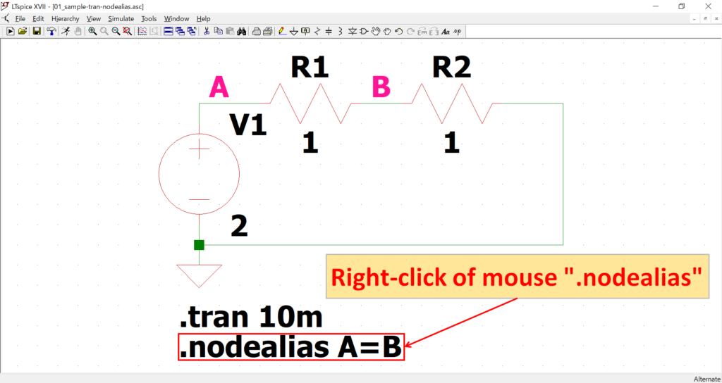
Right click on ".nodealias".
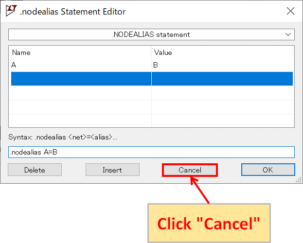
The ".nodealias Statement Editor" allows editing of the ".nodealias" syntax.
In this case, we will not use this feature, so click "Cancel".
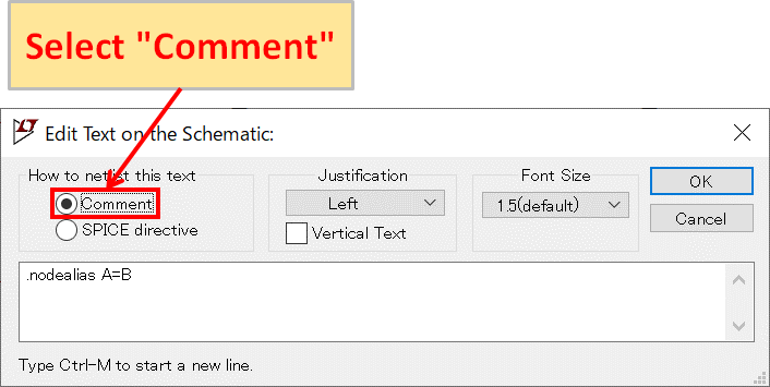
Since "SPICE directive" is selected, select "Comment".
After changing the selection, click "OK.
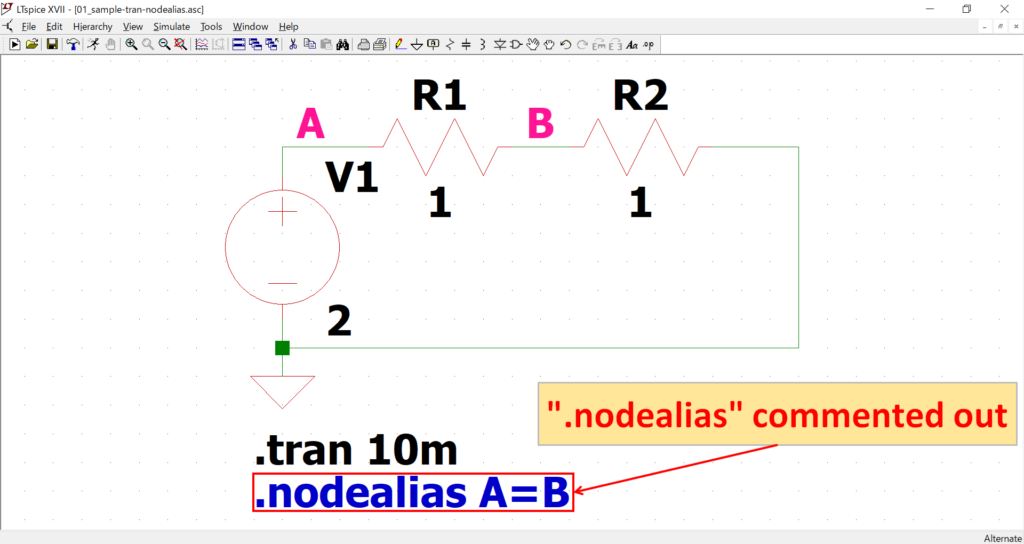
Now, ".nodealias" is commented out and changes to blue text, and nodes "A" and "B" are back to their unconnected state.
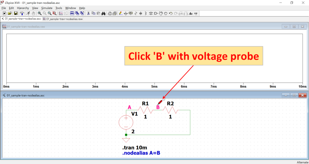
Check if ".nodealias" is disabled.
Move the mouse cursor to node "B" to switch to the voltage probe and click on it.

The voltage value of node "B" is 1[V] because 2[V] of the supply voltage is divided by 1/2 by resistors "R1" and "R2".
We could check if ".nodealias" is disabled. Of course, you could have removed the command itself, but this clever use of commenting out makes it easy to switch the connection.
The schematic used for this simulation of ".nodealias" can be downloaded from the following link.