LTspice-How to Draw a Schematic
After all, in order to learn how to use LTspice, it should be faster to use the practice form and to learn first than to read the instruction manual.
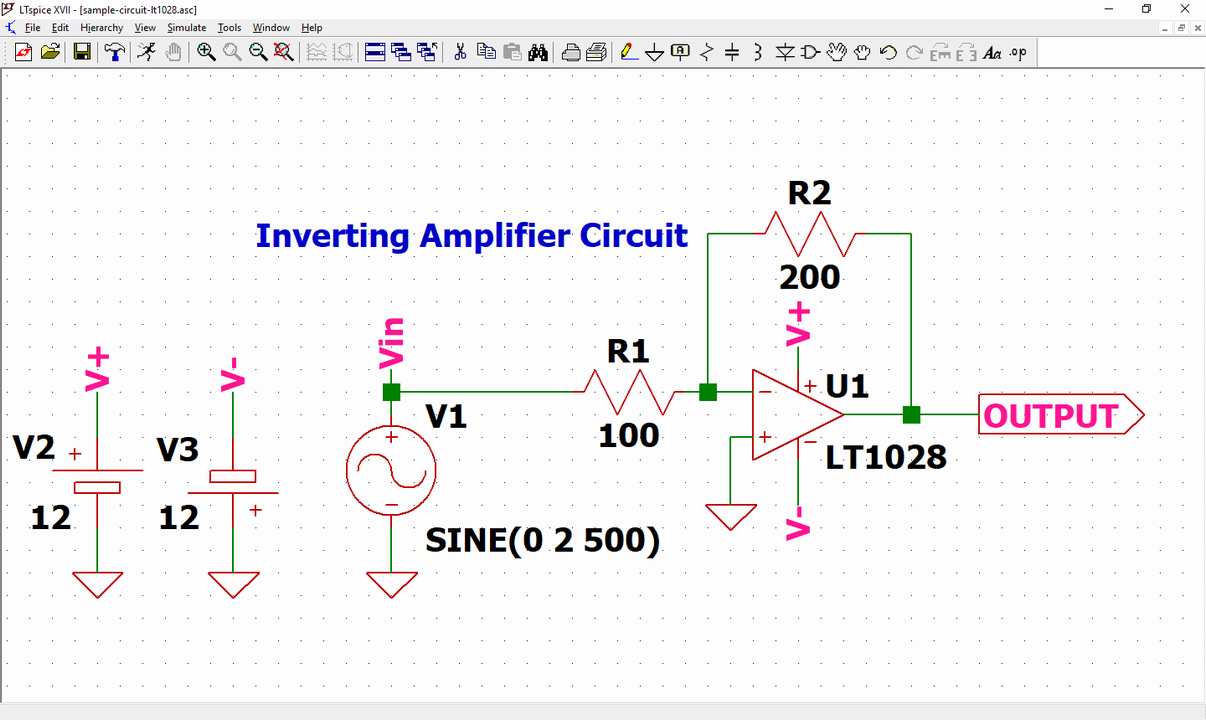
In this article, we will learn how to draw a schematic with LTspice, using the "Inverting Amplifier Circuit".
How to use LTspice's commands for drawing schematics is summarized in the following article. Please refer to if there is something you do not understand in detail.
Open the Schematic Editor
First let's open the schematic editor to draw a schematic with LTspice.
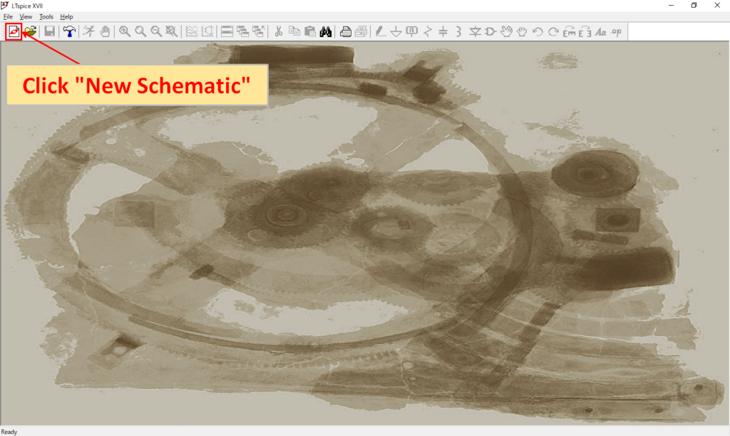
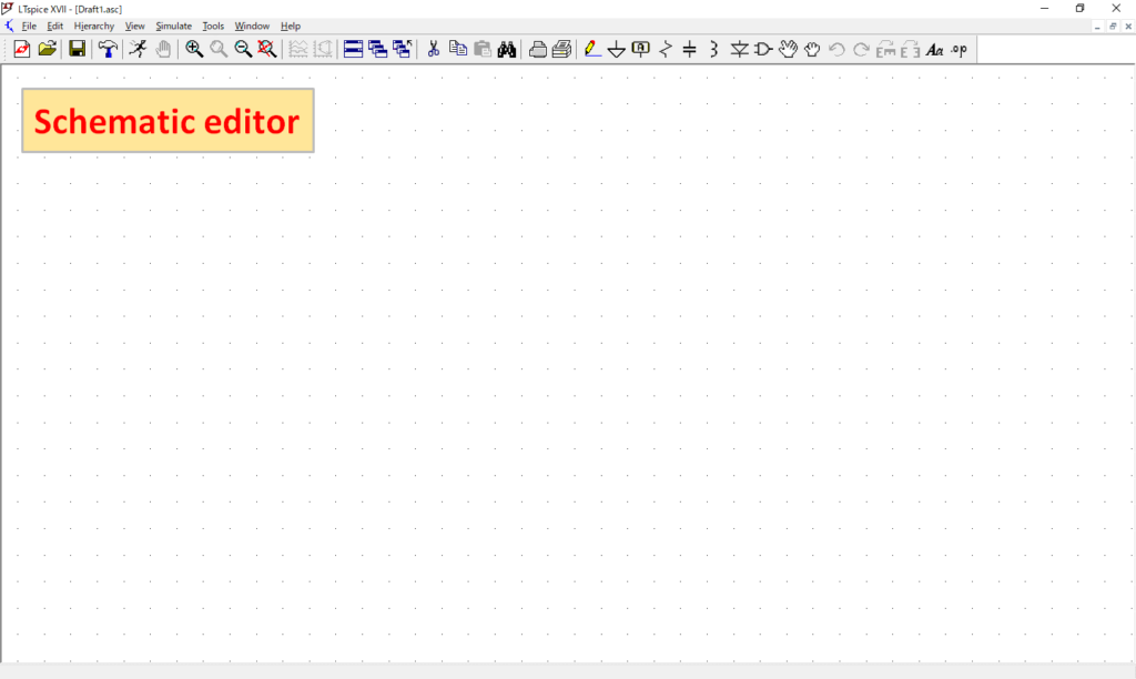
Launch LTspice and click "New Schematic" on the left side of the initial screen toolbar to open the schematic editor.
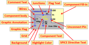
In this article, the settings have been changed to "the background is white" and "check grid" in the schematic editor to make it easy to see.
If you do not have the initial settings because it is easy to use, please refer to the following article to change the settings.
Parts Placement and Wiring
First, we will place the parts used for the inverting amplifier circuit. It would be easier to draw a schematic if you placed the op-amp in the center and then placed a resistors etc around it.
Operational Amplifier Placement
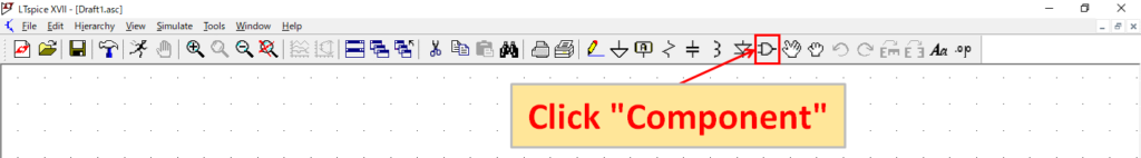
Click "Component" from the toolbar of the schematic editor.
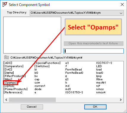
Select "Opamps" and click "OK" or double-click "Opamps".
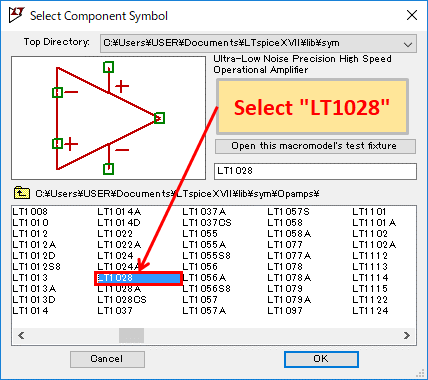
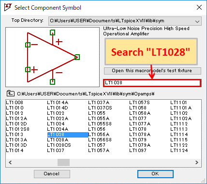
Select "LT1028" and click "OK" or double-click "LT1028".
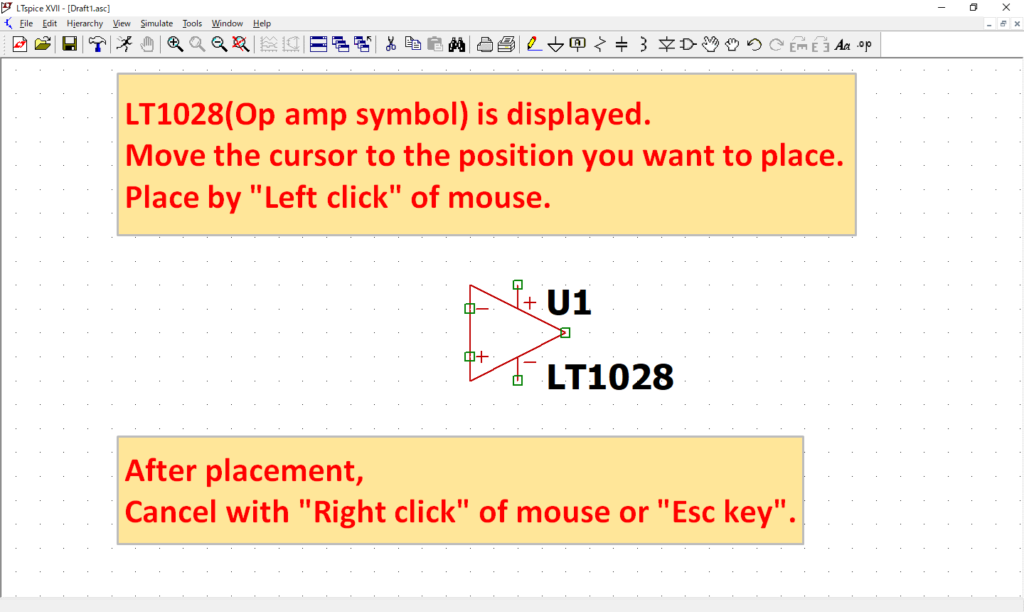
Since LT1028 (Op amp symbol) is displayed, move the cursor to the position where you want to place it, and place it with "Left click" of the mouse.
After placement, cancel the placement of the part with "Right click" of the mouse or "Esc key" on the keyboard.
In addition to searching for parts by group (classification), there is also a way to search for parts.
If you already know the model number, searching is easier. For example, if you enter “LT1028” in the search window, you can find it as follows.
Resistance Placement
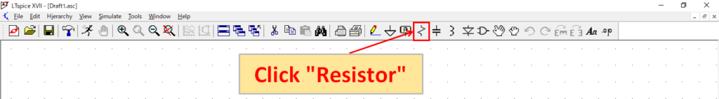
Click “Resistor” from the schematic editor toolbar.
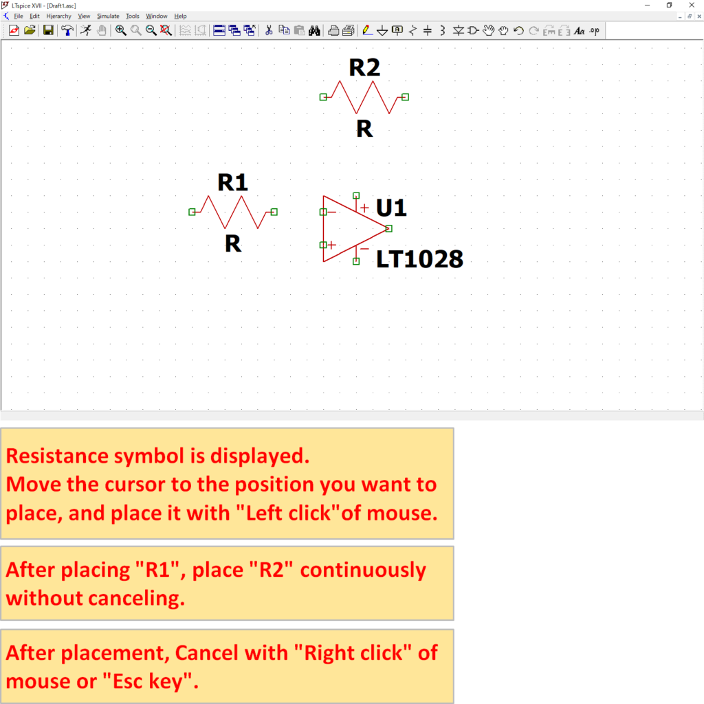
As the symbol of resistance is displayed, move the cursor to the position where you want to place it, and place it with “Left click” of the mouse.
Since the resistors are placed continuously, after placement of “R1”, place “R2” continuously without canceling the component placement.
After placement, cancel the placement of the part with “Right click” of the mouse or “Esc key” on the keyboard.
Signal Source Placement
Click "Component" from the toolbar of the schematic editor.
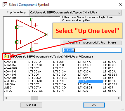
Click "Up One Level" to go back one level higher.
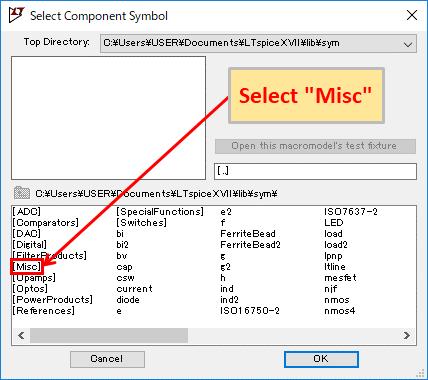
Select "Misc" and click "OK" or double-click of the mouse "Misc".
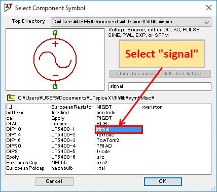
Select "signal" and click "OK" or double-click of the mouse "signal".

As the symbol of the signal source is displayed, move the cursor to the position where you want to place it, and place it with the "Left click" of the mouse.
After placement, cancel the placement of the part with "Right click" of the mouse or "Esc key" on the keyboard.
Cell Placement
Click "Component" from the toolbar of the schematic editor.
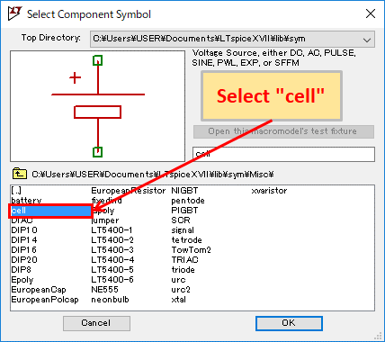
Select "cell" and click "OK" or double-click "cell" of the mouse.
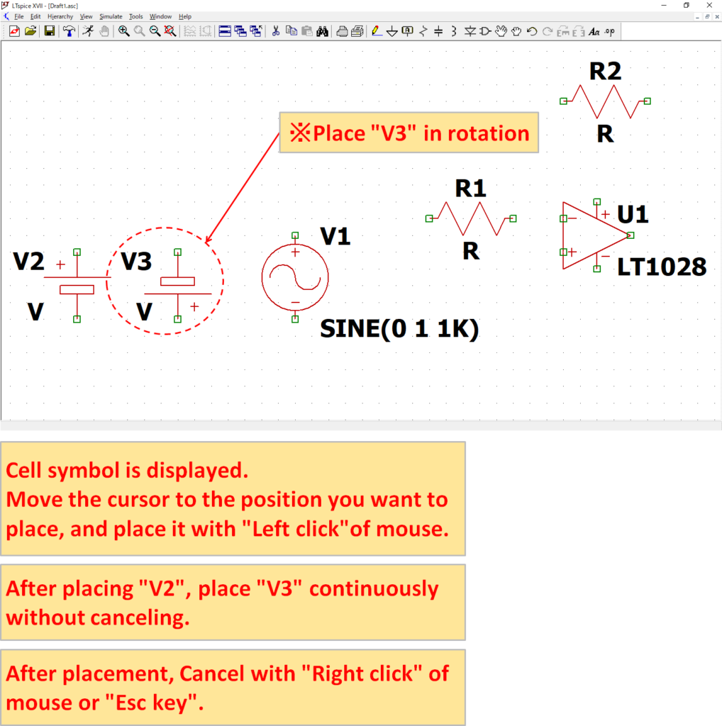
The cell symbol will be displayed, so move the cursor to the position where you want to place it and place it with "Left click" of the mouse.
Since the cell supply is continuously placed, after placement of "V2", place "V3" continuously without canceling the part placement. Rotate "V3" with the command of the toolbar or the keyboard shortcut and place it so that + side is down.
After placement, cancel the placement of the part with "Right click" of the mouse or "Esc key" on the keyboard.
The power supply "V3" rotates so that the + power supply side is up and the + power supply side is down.
You can use the "Rotate" and "Mirror" commands on the toolbar to rotate and flip parts, but it is more convenient to use keyboard shortcuts.
In the default keyboard shortcut settings, rotation of parts can be operated with "Ctrl + R" and flipping of parts with "Ctrl + E".
Parts rotation / mirror
| Command | Explanation | Menu bar icon | Shortcut keyboard |
|---|---|---|---|
| Rotate | Rotate parts |   | Ctrl+R |
| Mirror | Flip parts |  | Ctrl+E |
Refer to the following article about the setting of the recommended keyboard shortcut.
GND Placement
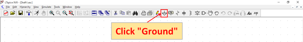
Click "Ground" from the toolbar of the schematic editor.
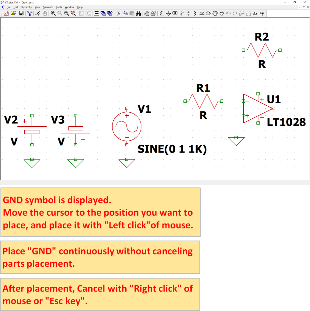
Since the GND symbol is displayed, move the cursor to the position where you want to place it, and place it with "Left click" of the mouse.
Since GND are continuously placed, "GND" are continuously placed without canceling the component placement.
After placement, cancel the placement of the part with "Right click" of the mouse or "Esc key" on the keyboard.
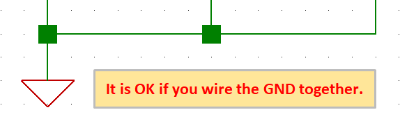
When simulating, LTspice always uses GND as the reference point for potential.
There is no problem if one GND symbol is placed and wired together as shown below. The wiring will be described in detail in the next section.
Wiring
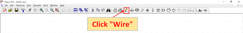
Click "Wire" from the toolbar of the schematic editor.
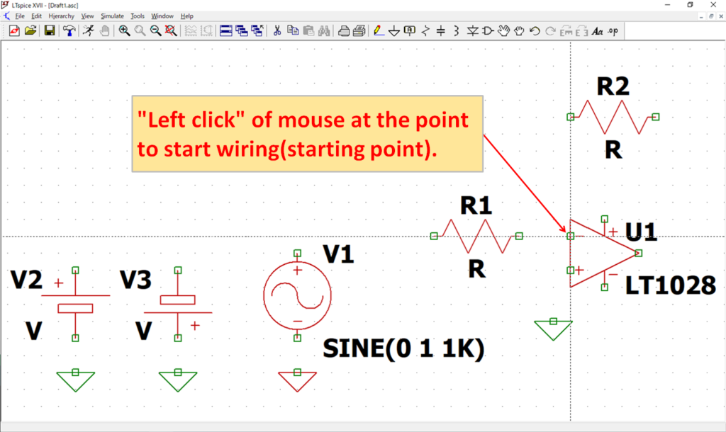
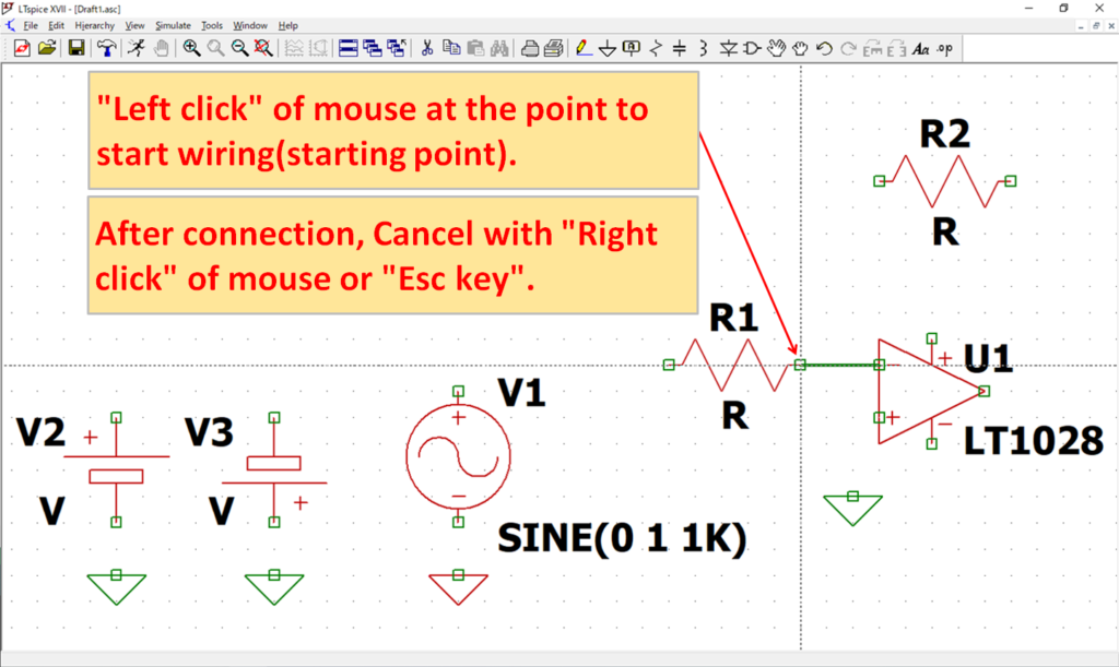
"Left click" of the mouse on the point (start point) where you want to start wiring.
"Left click" of the mouse where you want to end the wiring (end point).
After wiring, cancel the wiring with "Right click" of the mouse or "Esc key" on the keyboard.
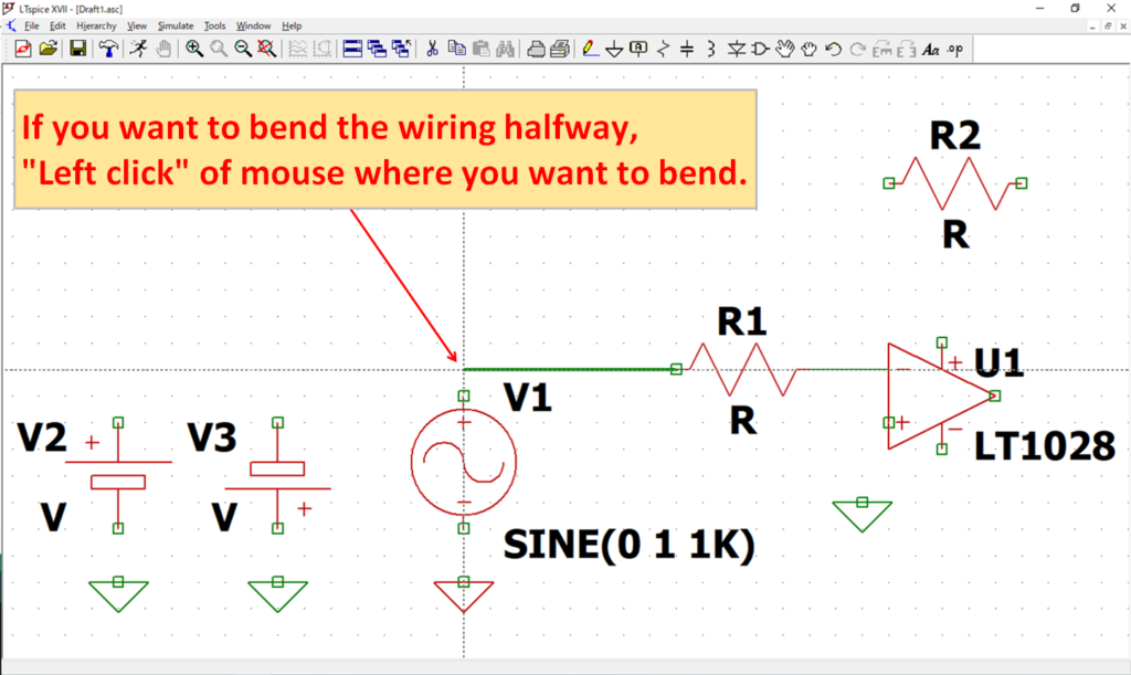
If you want to bend the wire, "Left click" the start of the wire with the mouse and then "Left click" with the mouse at the point where you want to bend the wire.
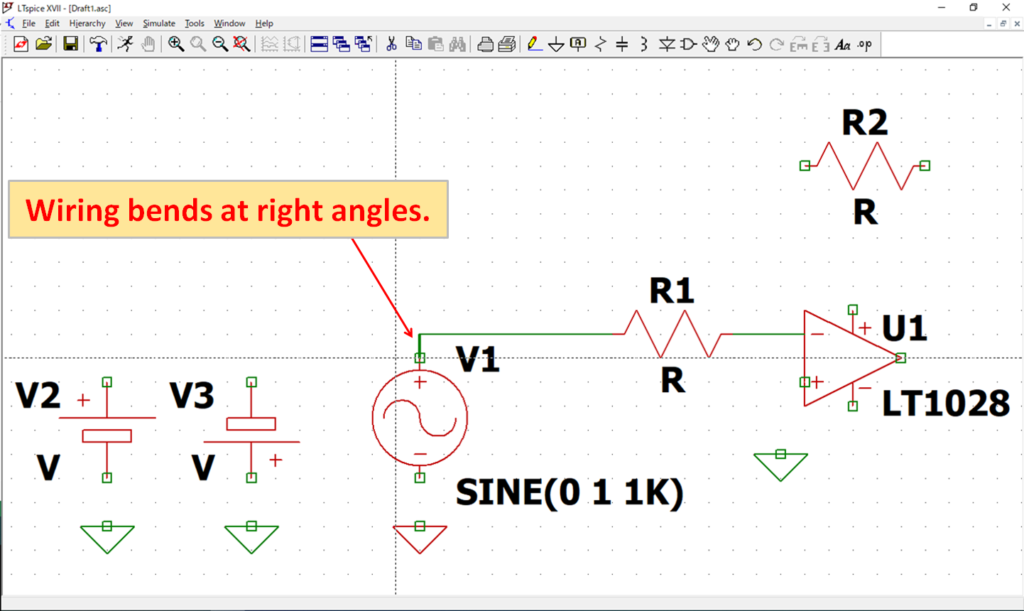
As the wire bends at right angles, "Left click" of the mouse at the end of the wire.
By default setting, LTspice XVII can pierce and connect components when wiring as follows (overlap).
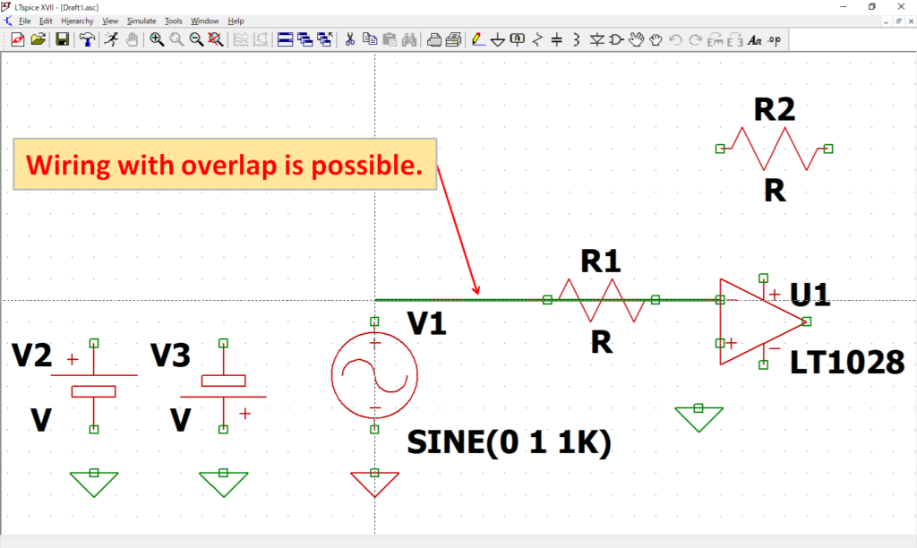
The wiring in the overlap is quicker, so be sure to remember.
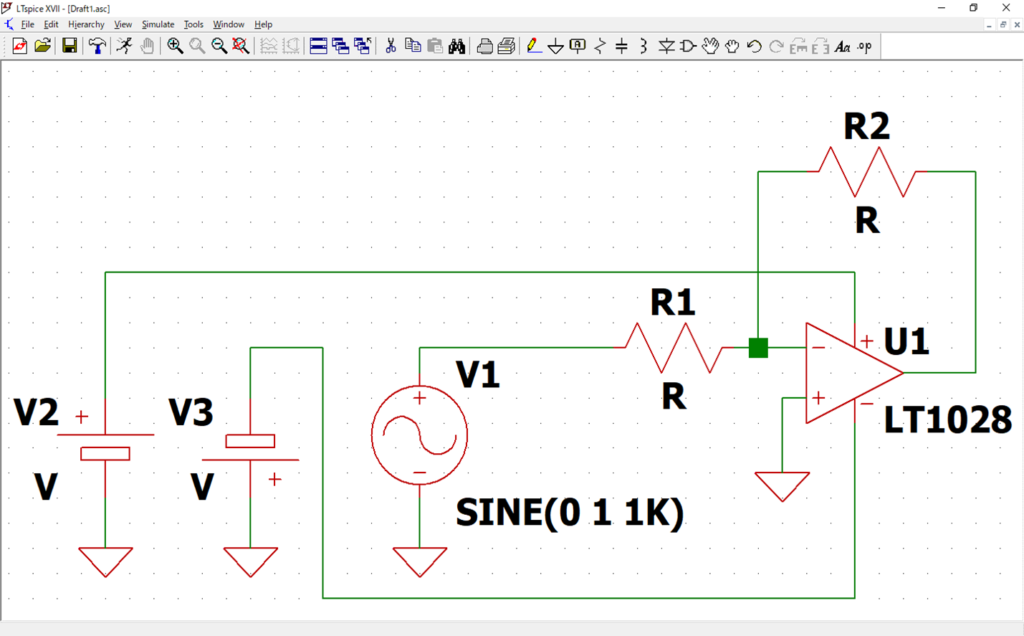
After learning how to wire, try wiring as shown in the schematic above. If the wires are connected, they are displayed as "■".
Parts Movement
This section explains parts movement. Broadly speaking, there are "Move" and "Drag" commands.
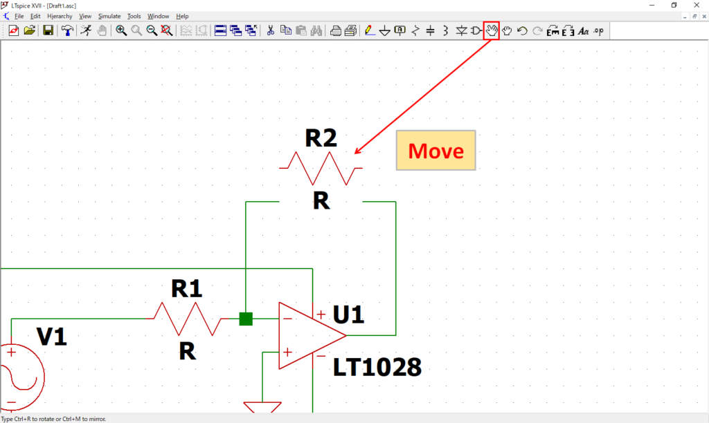
From the tool bar of the schematic editor, click "Move" and "Left click" of the mouse on the hand mark on the part to move the selected part only.
(The part within the specified range can be moved collectively by holding the left mouse button and surrounding parts.)
After the move, you can cancel the part move with "Right click" of the mouse or "Esc key" on the keyboard.

From the tool bar of the schematic editor, click “Drag” and “Left click” of the mouse the fist mark on the part to move the selected part along with the wiring.
(You can move parts in a specified range at once by holding the left mouse button and surrounding parts.)
After the move, you can cancel the part move with "Right click" of the mouse or "Esc key" on the keyboard.
Delete Parts
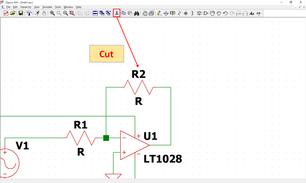
From the schematic editor toolbar, click "Cut" and "Left click" of the mouse over the part with the scissors mark.
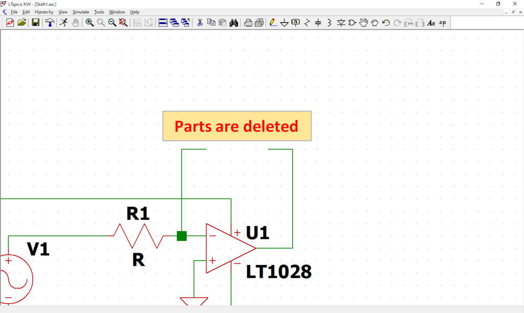
You can see that the selected part has been deleted. Not only parts but also wiring can be deleted.
Edit parts
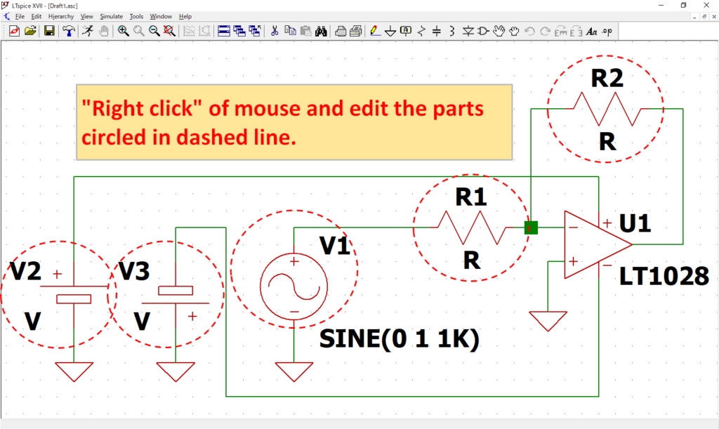
After placing and wiring the parts, let's enter the parameters in "Edit Part". You can edit the part by "Right-clicking" the part with the mouse.
Edit Resistance
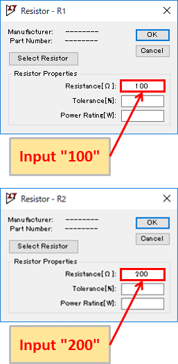
Input "100" and "200" for the Resistance [Ω] of R1 and R2, respectively.
LTspice is not case sensitive, so if you enter "M(106)", it will be recognized as "m(10-3)".
Therefore, please enter "Meg(3 letters)" in this case.
Also, use caution as "u" is used instead of "μ(micro)".
Auxiliary unit of LTspice
| Unit (prefix) | Unit | Multiple |
|---|---|---|
| T | tera | 1012 |
| G | giga | 109 |
| Meg | mega | 106 |
| k | kilo | 103 |
| m | milli | 10-3 |
| u | micro | 10-6 |
| n | nano | 10-9 |
| p | pico | 10-12 |
| f | femto | 10-15 |
Edit Signal Source
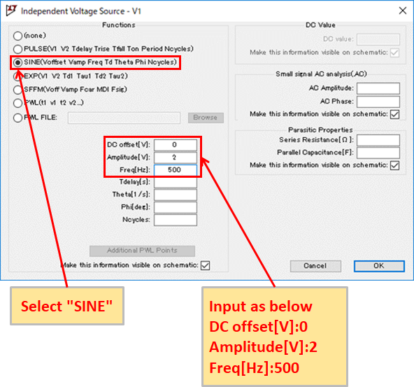
Select "SINE" and enter "DC offset [V]: 0", "Amplitude [V]: 2", "Freq [Hz]: 500".
Edit Cell
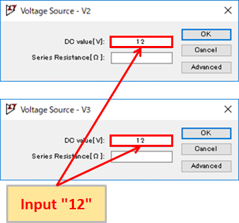
Enter "12" for DC value [V] of V2 and V3 respectively.
Add Label Net
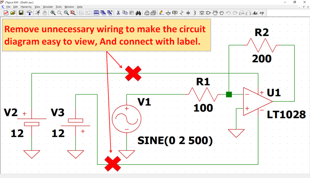
It has been completed as a circuit diagram, but the wiring is messy and hard to see.
To make it easier to see the schematic, try removing and labeling unnecessary wiring.
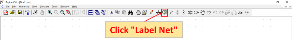
Click "Label Net" from the toolbar of the schematic editor.
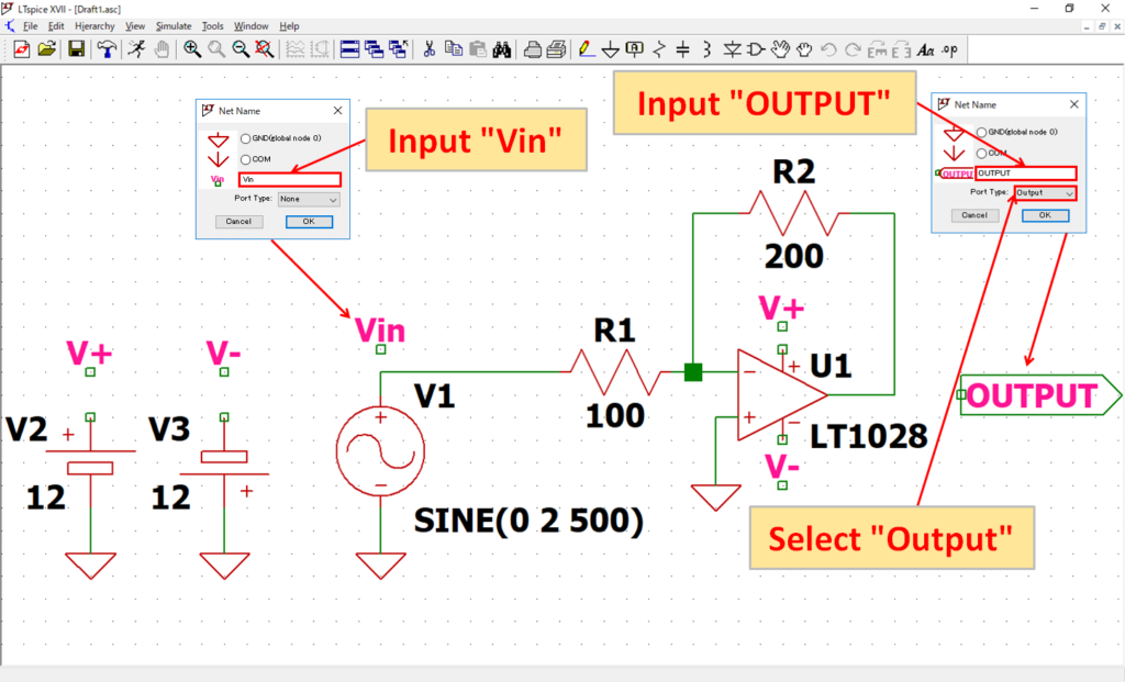
Place the label "Vin" above V1.
Also, select “Output” for Part Type, and place a label with “OUTPUT” on the output side of the op amp.
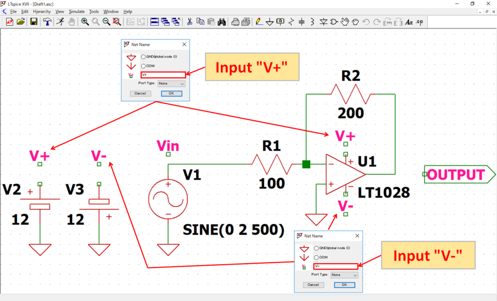
Place the label "V+" on the + sides of V2 and U1, and place the label "V-" on the -sides of V3 and U1.
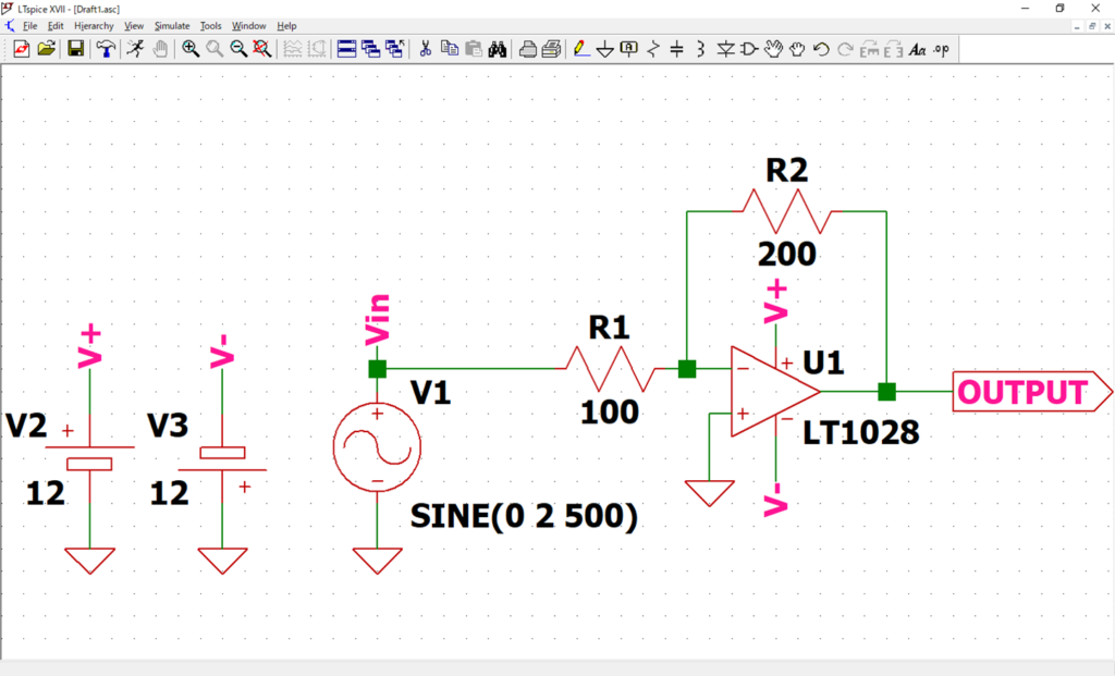
After placing the labels, wire the labels as shown in the schematic above.
The placement of the "V+" and "V-" labels made the wiring clearer and easier to see.
Also, as explained in the other article in detail, the waveform graph in simulation is displayed with label names, so it is easy to understand.
Input Comment on the Schematic
Although it is not essential, I think that it is easier to comment the circuit name in the schematic.
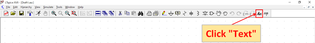
Click "Text" from the toolbar of the schematic editor.
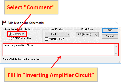
Select "Comment" and enter "Inverting Amplifier Circuit".
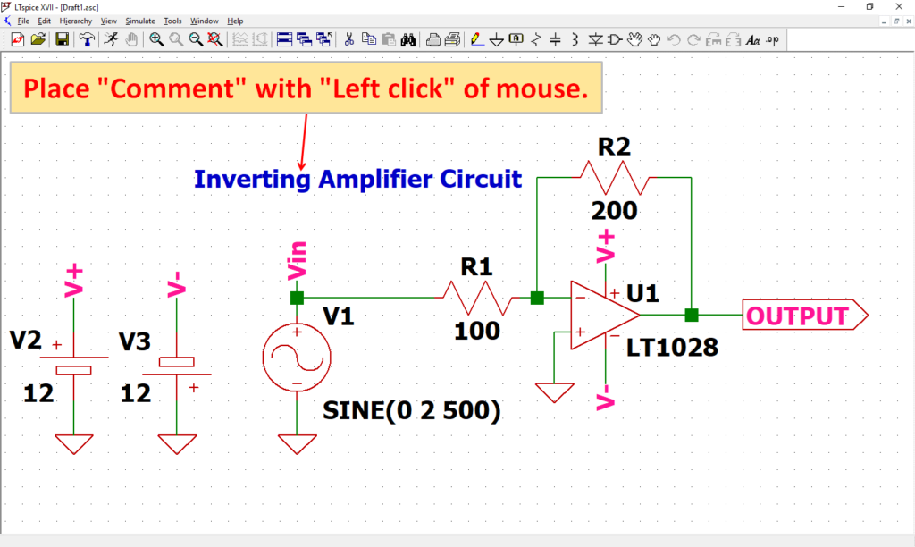
Placement does not have any problem in one's favorite place. This time, place it by the "Left click" of the mouse above the schematic.
Be assured that comments on the circuit diagram will not affect the execution of the simulation.
Save Schematic File
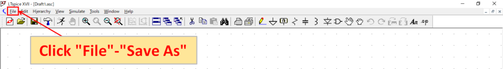
From the menu bar of the schematic editor, click "File"-"Save As".
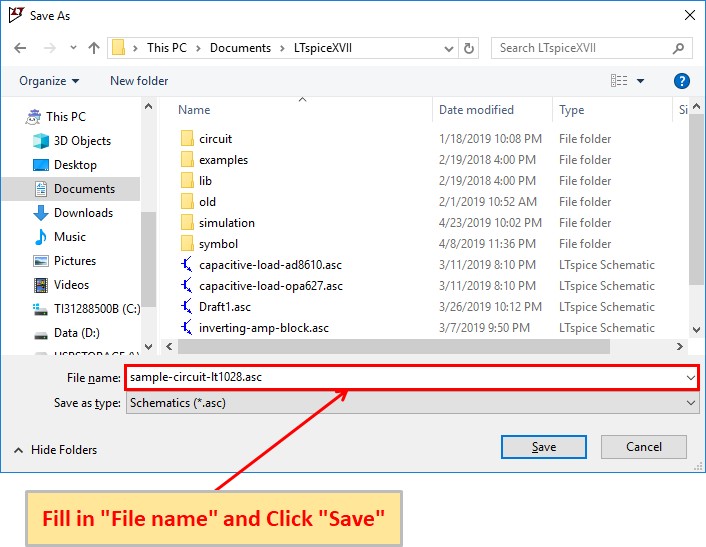
Fill in the file name, select the location you want to save and save it.
This time, I saved the file name as "sample-circuit-lt1028.asc".
Unfortunately, even the latest version of LTspice XVII, like Microsoft Office Word and Excel, does not automatically save backup.
It is important to save frequently if the circuit scale is large, in case the PC freezes due to any accident, etc., the schematic data in process of creation will disappear.
Analysis Types
In this article, we have explained how to create a schematic, but we will also explain various types of analysis through simulation using this schematic.
Please see the following article for details.