LTspice-How to Operate Commands for a Schematic

In this article, I will introduce LTspice XVII's "Commands for drawing schematics".
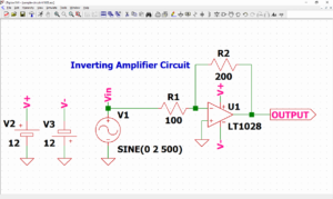
If you want to learn how to make a circuit diagram with LTspice XVII, I recommend that you first make a circuit diagram and keep in mind while referring to the following article.
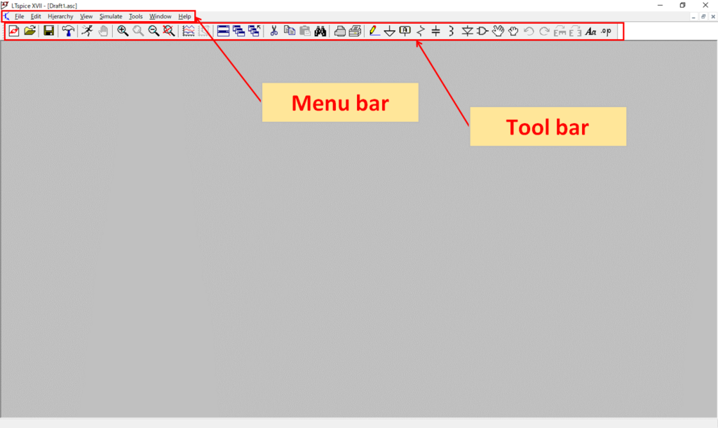
Commands on the initial screen
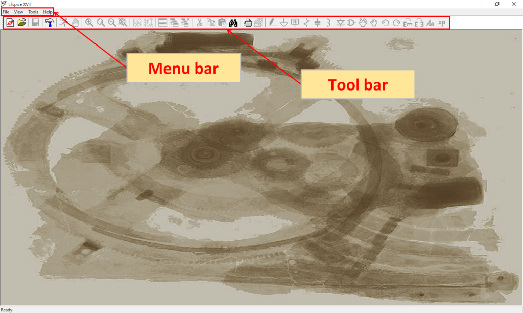
Menu bar
File
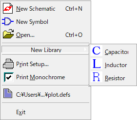
| File | Explanation |
|---|---|
| New Schematic | Create a new schematic |
| New Symbol | Create a new symbol |
| Open… | Open existing file |
| New Library -Capacitor | Create a new library of capacitor device models |
| New Library -Inductor | Create a new library of inductor device models |
| New Library -Resistor | Create a new library of resistor device models |
| Print Setup | Printer settings |
| Print Monochrome | Setting for black and white printing |
| "Recent Files" Example C:¥Users¥…¥plot.defs | Open "Recent Files" |
| Exit | Exit LTspice |
View
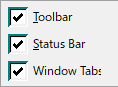
| View | Explanation |
|---|---|
| Toolbar | Display toolbar when checked |
| Status Bar | Display status bar when checked |
| Windows Tabs | Display windows tabs when checked |
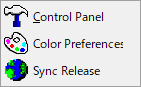
Tools
| Tools | Explanation |
|---|---|
| Control Panel | Open control panel (Various settings of LTspice are possible) |
| Color Preference | Open color palette Editor (Color change of the screen of LTspice is possible) |
| Sync Release | Update of LTspice programs and model libraries |
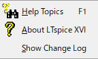
Help
| Help | Explanation |
|---|---|
| Help Topics | Open help file |
| About LTspice ⅩⅤⅡ | Display version information of LTspice |
| ShowChange Log | Display LTspice's program update history |
Tool bar

| Icon | Tool bar Menu | Explanation |
|---|---|---|
 | New Schematic | Create a new schematic |
 | Open | Open existing file |
 | Control Panel | Open control panel (Various settings of LTspice are possible) |
 | Search | Search for letters on schematic (The color of the corresponding part changes) |
Commands on the Schematic editor
Menu bar
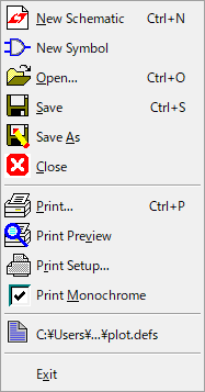
File
| File | Explanation |
|---|---|
| New Schematic | Create a new schematic |
| New Symbol | Create a new symbol |
| Open… | Open existing file |
| Save | Overwrite save |
| Save As | Save as |
| Close | Close open file |
| Print… | Print configuration |
| Print Preview | Print preview |
| Print Setup… | Printer settings |
| Print Monochrome | Setting for black and white printing |
| “Recent Files” Example C:¥Users¥…¥plot.defs | Open “Recent Files” |
| Exit | Exit LTspice |
Edit
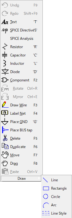
| Edit | Explanation |
|---|---|
| Undo | Cancel operation |
| Redo | Redo operation |
| Text | Place text |
| SPICE Directive'S' | Enter dot command |
| SPICE Analysis | Enter simulation command |
| Resistor | Place resistance |
| Capacitor | Place capacitor |
| Inductor | Place inductor |
| Diode | Place diode |
| Component | Place various parts (Select from "Select Component Symbol") |
| Rotate | Rotate parts |
| Mirror | Flip parts |
| Draw Wire | Draw wire |
| Label Net | Name the node |
| Place GND | Place GND |
| Place BUS tap | Do the BUS wiring |
| Delete | Delete parts and wiring etc. |
| Duplicate | Duplicate parts and wiring etc. |
| Move | Move parts and wiring etc. |
| Drag | Move parts with wiring |
| Paste | Place the copied parts and wiring etc. |
| Draw -Line | Draw a line |
| Draw -Rectangle | Draw a rectangle |
| Draw -Circle | Draw a circle |
| Draw -Arc | Draw a circular |
| Draw -Line Style | Select line type |
In LTspice, it is possible to make multiple wiring into BUS wiring.
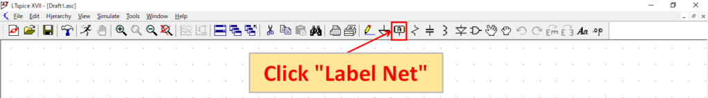
Click "Label Net" on the toolbar.
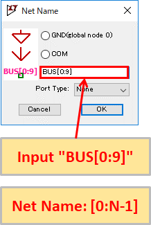
Set the number of BUS wiring you want to create in the format of Net name "[0:N-1]". For example, if you want to make "10 BUS wiring" with "Net name: BUS", it will be "BUS[0:9]".
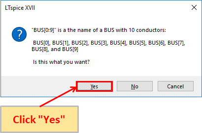
A screen will appear asking you to confirm the BUS wiring configuration. Click "Yes".
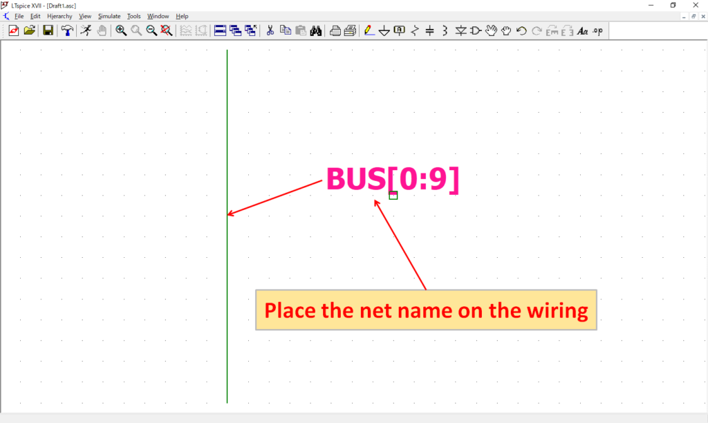
Place the Net name on the wiring that you want to make the BUS wiring.
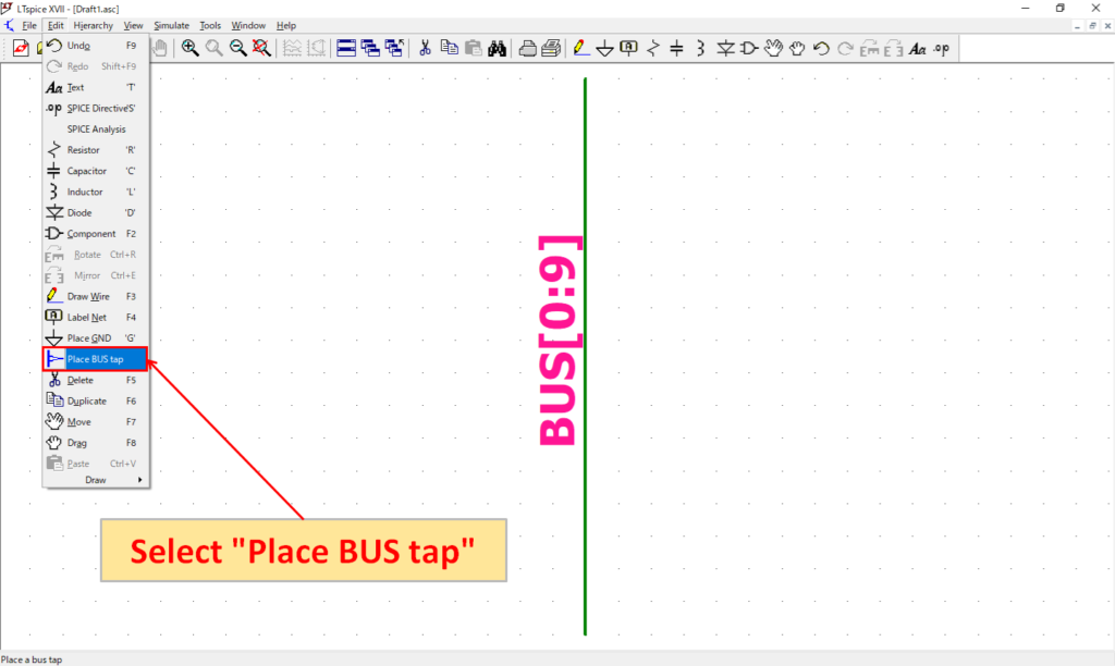
Select "Edit"-"Place BUS tap".
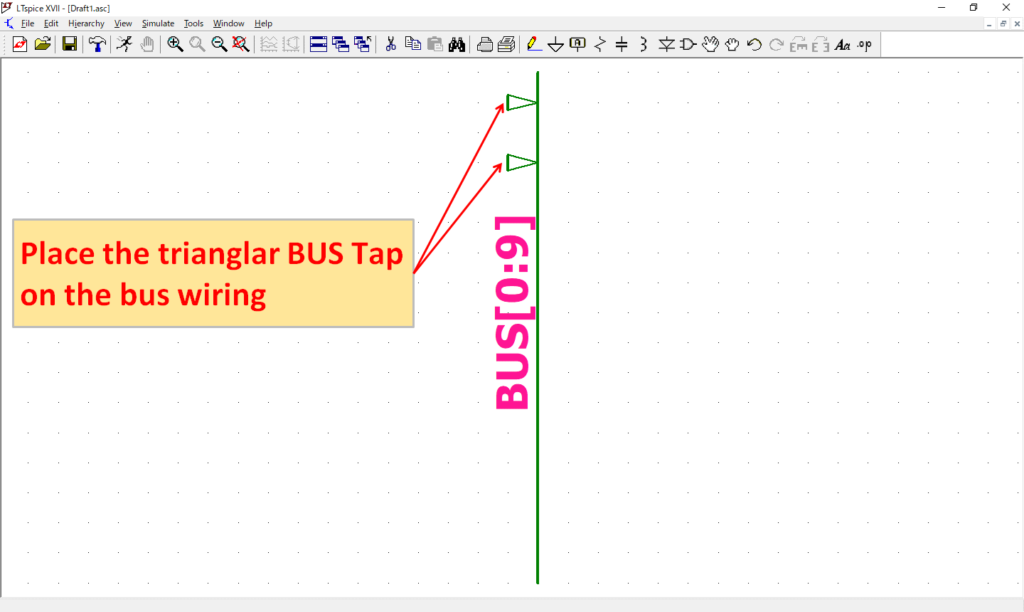
Place the trianglar BUS tap that branches the bus wiring at an appropriate position. BUS tap can also be rotated and inverted.
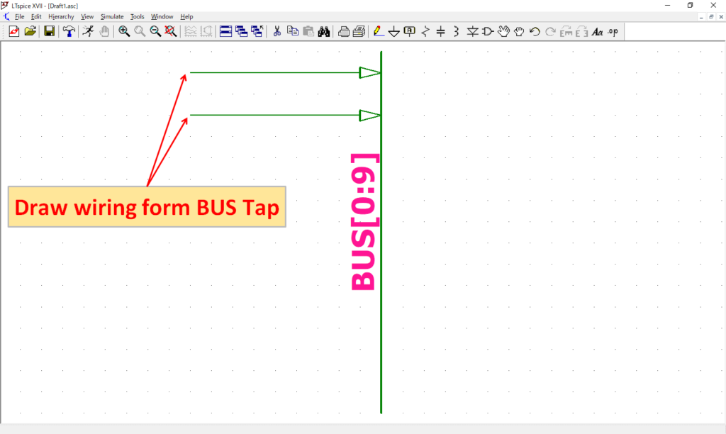
Draw the wiring from the BUS tap.
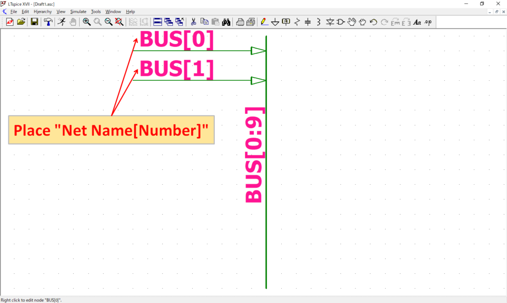
Place "Net name[number]" because you can not identify which line it is only by drawing a line from BUS tap. For example, the first bus wiring is BUS [0].
Hierarchy
| Hierarchy | Explanation |
|---|---|
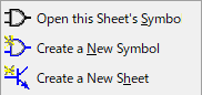
| Open this Sheet's Symbol | Create symbols of circuit diagram |
| Create a New Symbol | Create a new symbol |
| Create a New Sheet | Create a new schematic editor |
View
| View | Explanation |
|---|---|
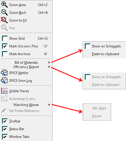
| Zoom Area | Zoom in |
| Zoom Back | Zoom out |
| Zoom to Fit | Auto scale |
| Pan | Set reference point of display |
| Show Grid | Display grid when checked |
| Mark Unconn. Pins | Display empty pins when checked |
| Mark Anchors | Display the reference point of the object when checked |
| Bill of Materials -Show on Schematic | Display the bill of materials for the schematic |
| Bill of Materials -Paste to clipboard | Copy the schematic bill of materials to the clipboard |
| Efficiency Report -Show on Schematic | Display efficiency report |
| Efficiency Report -Paste to clipboard | Copy efficiency report to clipboard |
| SPICE Netlist | Display net list of schematic |
| SPICE Error Log | Display log file of simulation results |
| Visible Traces | Display waveform graph |
| Autorange Y-axis | Autorange of Y axis scale of waveform graph |
| Marching Waves -(Re-)Start | Display the waveform as it travels |
| Marching Waves -Pause | Pause to display the waveform as it travels |
| Set Probe Reference | Change the reference point of the probe |
| Toolbar | Display toolbar when checked |
| Status Bar | Display status bar when checked |
| Window Tabs | Display windows tabs when checked |
Simulate
| Simulate | Explanation |
|---|---|
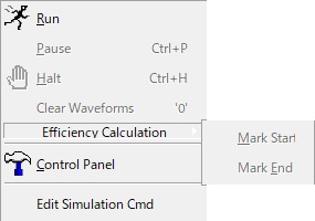
| Run | Start simulation |
| Pause | Pause simulation |
| Halt | Stop simulation |
| Clear Waveforms | Clear waveforms |
| Efficiency Calculation -Mark Start | |
| Efficiency Calculation -Mark End | |
| Control Panel | Open Control Panel (Various settings of LTspice are possible) |
| Edit Simulation Cmd | Open "Edit Simulation Cmd" |
Tools
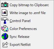
| Tools | Explanation |
|---|---|
| Copy bitmap to Clipboard | Copy screen to clipboard in BMP format |
| Write image to .emf file | Save schematic in emf format |
| Control Panel | Open control panel (Various settings of LTspice are possible) |
| Color Preferences | Open color palette Editor (Color change of the screen of LTspice is possible) |
| Sync Release | Update of LTspice programs and model libraries |
| Export Netlist | Save netlist for printed circuit board creation |
Window
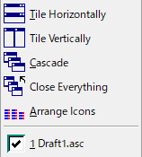
| Window | Explanation |
|---|---|
| Tile Horizontally | Place the screen on the left and right |
| Tile Vertically | Place the screen up and down |
| Cascade | Place the screen overlapping |
| Close Everything | Close all the screens |
| Arrange Icons | Arrange the minimized screens(icons) on the bottom left |
| Schematic file currently open Example Draft1.asc | Change schematic file |
Help
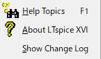
| Help | Explanation |
|---|---|
| Help Topics | Open help file |
| About LTspice ⅩⅤⅡ | Display version information of LTspice |
| Show Change Log | Display LTspice’s program update history |
Tool bar

| Icon | Tool bar Menu | Explanation |
|---|---|---|
 | New Schematic | Create a new schematic |
 | Open | Open existing file |
 | Save | Overwrite save |
 | Control Panel | Open Control Panel (Various settings of LTspice are possible) |
 | Run | Start simulation |
 | Halt | Pause simulation |
 | Zoom to rectangle | Zoom in |
 | Pan | Set reference point of display |
 | Zoom Back | Zoom out |
 | Zoom full extents | Auto scale |
 | Pick Visible Traces | Display waveform graph |
 | Autorange | Autorange of Y axis scale of waveform graph |
 | Tile Windows | Place the screen on the left and right |
 | Cascade Windows | Place the screen overlapping |
 | Close All | Close all the screens |
 | Cut | Delete parts and wiring etc. |
 | Copy | Copy parts and wiring etc. |
 | Paste | - |
 | Search | Search for letters on schematic (The color of the corresponding part changes) |
 | Print Setup | Printer settings |
 | Print configuration | |
 | Wire | Draw wire |
 | Ground | Place GND |
 | Label Net | Name the node |
 | Resistor | Place resistance |
 | Capacitor | Place capacitor |
 | Inductor | Place inductor |
 | Diode | Place diode |
 | Component | Place various parts (Select from “Select Component Symbol”) |
 | Move | Move parts and wiring etc. |
 | Drag | Move parts with wiring |
 | Undo | Cancel operation |
 | Redo | Redo operation |
 | Rotate | Rotate parts |
 | Mirror | Flip parts |
 | Text | Place text |
 | SPICE Directive | Enter dot command |
Others
Multi monitor display
With LTspice XVII, it is possible to display screens such as the circuit diagram and waveform viewer separately. It can also be displayed on separate monitors as multiple monitors.
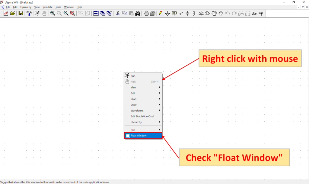
Right click of the mouse on the screen and check "Float Window".
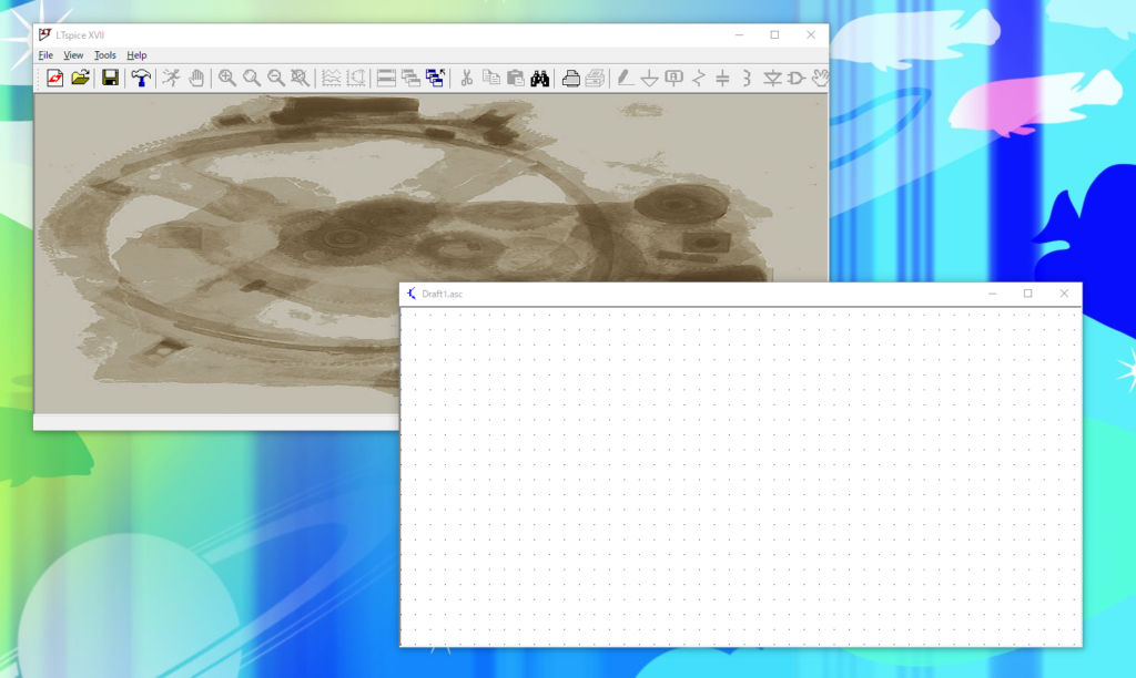
If you move the top of the screen checked in "Float Window" while pressing the left button of the mouse, you can display the screen separately as shown in the above picture.
Thumbnail display of file icon
By displaying thumbnails of LTspice's file icons, you can check the schematics and symbols in the file.
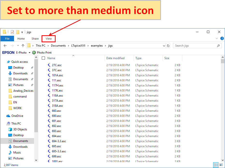
Open the folder where the LTspice file is saved, and set the icon type to "Medium icons or more" size from "View".
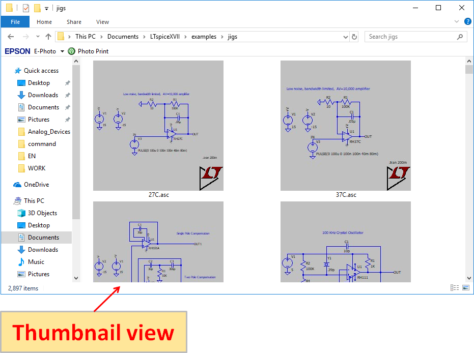
As shown in the above icons (set as an "Extra large icons"), thumbnails are displayed, making it easy to find the file.