.backanno : LTspice -- Annotate the Subcircuit Pin Names to the Port Currents

This article details the use of the dot command ".backanno".
The current flowing through the pins of a schematic symbol can be displayed on a graph using ".backanno".
".backanno" syntax
The ".backanno" syntax is as follows. You can now refer to the current flowing into the pins of the schematic symbol, and after the simulation is complete, left-click on the schematic symbol to display a graph of the current flowing into the pins.
After placement of schematic symbols or when simulation is run, a netlist is automatically generated and the ".backanno" syntax is automatically written.
Since there is no need to enter commands in "SPICE Directive", we rarely use ".backanno" consciously.
Examples of ".backanno" command
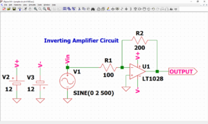
As an example of ".backanno" simulation, let's check if it is possible to graphically display the current flowing into the power supply in a circuit with only GND connected to the power supply.
Also, we will also check if it is possible to graphically display the current flowing into the resistor in a circuit where the resistor and power supply are connected.
In addition, if you have never created a schematic in LTspice, please refer to the following article.
First, let's see if ".backanno" is written to the netlist when the part is placed.
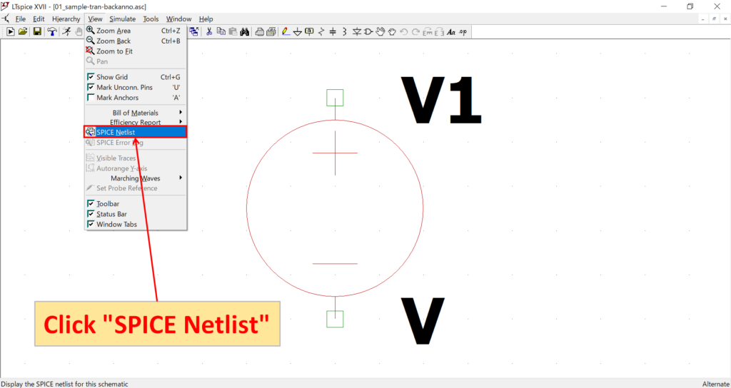
Select "voltage" from "Component" in the toolbar and place it on the schematic.
After placement, click "View"-"SPICE Netlist" on the menu bar.
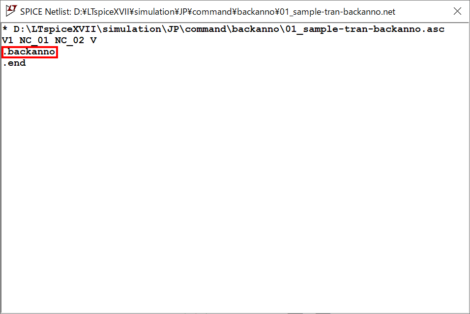
If you check the netlist, you will see that ".backanno" is described.
Thus, ".backanno" is automatically entered into the netlist and is rarely used consciously.
Next, to check if the current flowing into "V1" can be displayed graphically, connect GND to the voltage source "V1" and set the voltage value to 1[V] and the transient analysis to 10[ms].
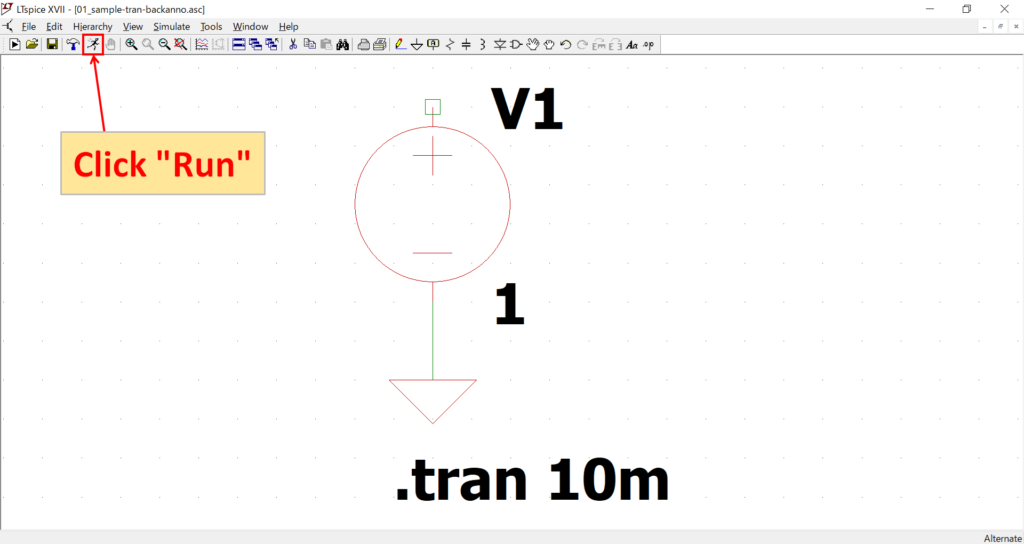
Click "Run" on the toolbar to run the simulation.
For a detailed explanation of transient analysis (.tran), please refer to the following article.
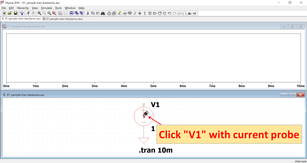
Move the mouse cursor to "V1" to switch to the current probe and click on it.
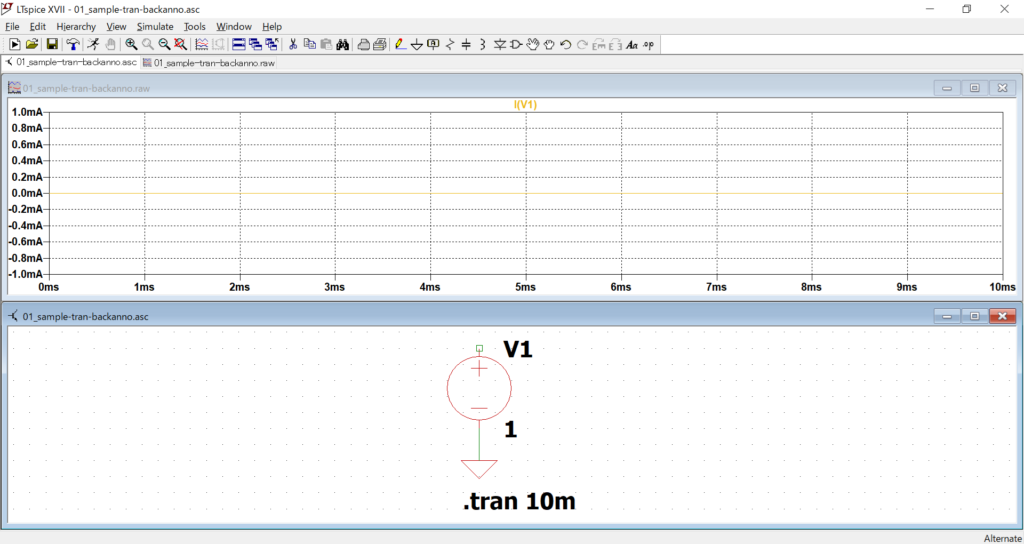
The graph displays the current flowing into "V1". Since nothing is connected to the voltage source "V1", it is 0[A].
Since it is difficult to image if the current is 0[A], let's connect 0[Ω] resistor "R1" to "V1" and display the current flowing into "R1" in a graph.
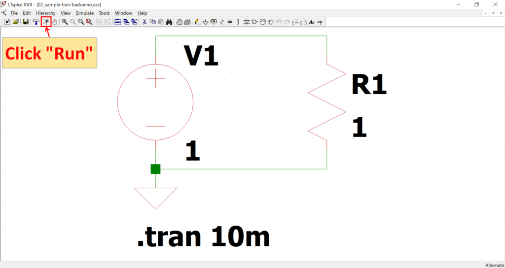
After creating the schematic, click "Run" on the toolbar.
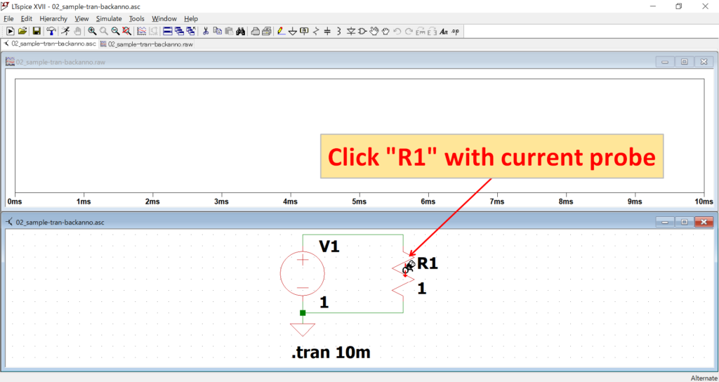
Move the mouse cursor to "R1" to switch to the current probe and click on it.
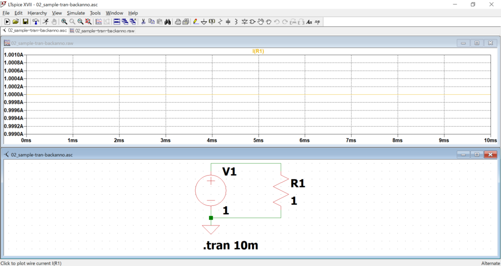
The graph displays the current flowing into "R1" and confirms that a current of 1[A] is flowing.
The schematic used for the ".backanno" simulation can be downloaded from the following link.