Op-Amp Summing Amplifier Circuit
In this article, "Op-Amp Summing Amplifier Circuit" will be explained in detail.
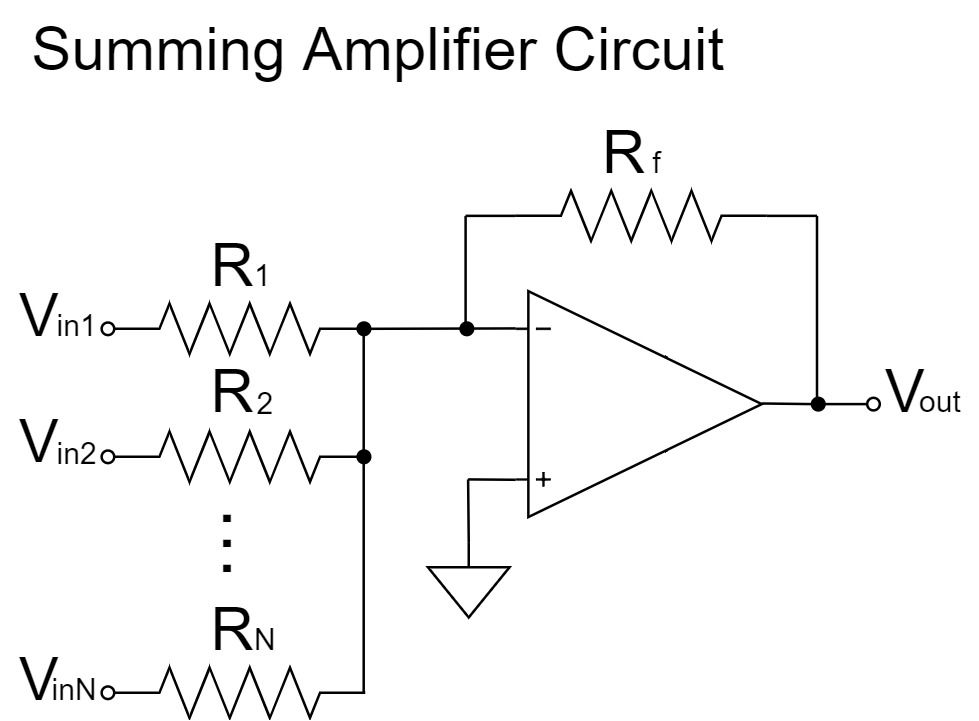
The summing amplifier circuit is a circuit that adds multiple input voltages together for output.
Op-Amp Summing Amplifier Characteristics
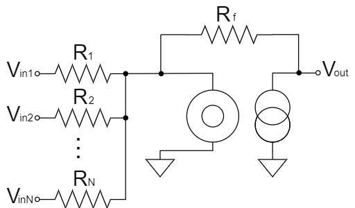
Summing Amplifier Circuit
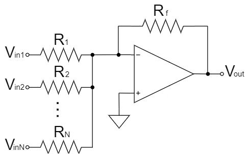
$$V_{out}=-\left(\frac{R_3}{R_1}V_{in1}+\frac{R_3}{R_2}V_{in2}+\cdots+\frac{R_f}{R_N}V_{inN}\right)$$
As shown above, the summing amplifier circuit outputs the sum of each $V_{inN}$ signal amplified by the amplification factor $\frac{R_f}{R_N}$ (weighting) to $V_{out}$. Also, the signal in $V_{out}$ is inverted.
If weighting by resistance ratio is not necessary, the output voltage can be easily calculated simply as the sum of the input voltages by setting $R_1=R_1=\cdots=R_N=R_f$ as shown below:
$$V_{out}=-(V_{in1}+V_{in2}+\cdots+V_{inN})$$
For example, if $N=3,V_{in1}=2V,V_{in2}=3V,V_{in3}=5V$;
$$V_{out}=-(V_{in1}+V_{in2}+V_{in3})=-(2+3+5)=-10[V]$$
Also, if $R_1=R_1=\cdots=R_N=R$ and $R_f=R/N$, the average of N input voltages can be obtained as an averager circuit.
$$V_{out}=-\left(\frac{\frac{R}{N}}{R}V_{in1}+\frac{\frac{R}{N}}{R}V_{in2}+\cdots+\frac{\frac{R}{N}}{R}V_{inN}\right)$$
$$V_{out}=-\left(\frac{1}{N}V_{in1}+\frac{1}{N}V_{in2}+\cdots+\frac{1}{N}V_{inN}\right)$$
$$V_{out}=-\frac{V_{in1}+V_{in2}+\cdots+V_{inN}}{N}$$
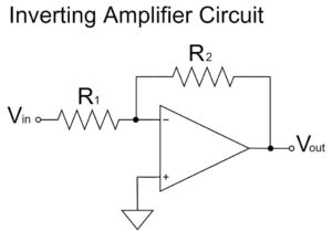
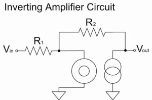
The summing amplifier circuit is an application of the inverting amplifier circuit, so when there is a single input voltage, the equation is for the inverting amplifier circuit.
$$V_{out}=-\left(\frac{R_f}{R_1}V_{in1}+\cancel{\frac{R_f}{R_2}V_{in2}}+\cdots+\cancel{\frac{R_f}{R_N}V_{inN}}\right)=-\frac{R_f}{R_1}V_{in1}$$
Therefore, it is better to understand the inverting amplifier circuit first, since the main features of the summing amplifier circuit and the inverting amplifier circuit are common.
Please refer to the following article for the calculation of the equation for the inverting amplifier circuit.
Op-Amp Summing Amplifier Equations(Formulas)
To obtain the equation for the op-amp summing amplifier circuit, the ideal op-amp is replaced by the nullor model.
Summing Amplifier Circuit
We replace the ideal op-amp with the nullor model and calculate the summing amplifier circuit as shown below:
The nullor model can represent a virtual short in an op amp, which simplifies the calculation.
For a more detailed explanation of the nullor model, please refer to the following article.
Summing Amplifier Circuit(Nullor Model)
We will try to change the above schematic for clarity.
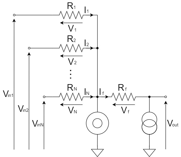
From Kirchhoff's Current Law(KCL), the relation between $I_f,I_1,I_2,I_N$ is:
$$I_f=I_1+I_2+\cdots+I_N$$
Also, $I_f,I_1,I_2,I_N$ are obtained as shown below.
$$I_1=\frac{V_1}{R_1}=\frac{V_{in1}}{R_1}\cdots(1) \qquad I_2=\frac{V_2}{R_2}=\frac{V_{in2}}{R_2}\cdots(2) \qquad I_N=\frac{V_N}{R_N}=\frac{V_{inN}}{R_N}\cdots(3)$$
$$I_f=\frac{V_f}{R_f}=\frac{-V_{out}}{R_f}=-\frac{V_{out}}{R_f}\cdots(4)$$
By substituting Eq.(1)-(4) into $I_f=I_1+I_2+\cdots+I_N$, the equation for the summing amplifier circuit is:
$$-\frac{V_{out}}{R_f}=\frac{V_{in1}}{R_1}+\frac{V_{in2}}{R_2}+\cdots+\frac{V_{inN}}{R_N}$$
$$V_{out}=-R_f\left(\frac{V_{in1}}{R_1}+\frac{V_{in2}}{R_2}+\cdots+\frac{V_{inN}}{R_N}\right)$$
$$V_{out}=-\left(\frac{R_f}{R_1}V_{in1}+\frac{R_f}{R_2}V_{in2}+\cdots+\frac{R_f}{R_N}V_{inN}\right)$$
Op-Amp Summing Amplifier with Non-inverted Output Signal
The summing amplifier circuit described so far is a circuit that applies the inverting amplifier circuit, so the output signal is inverted.
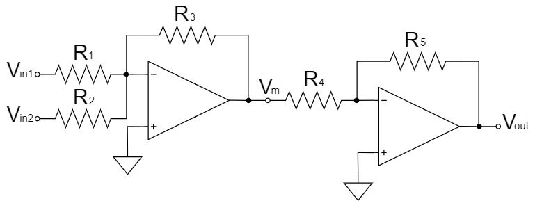
As shown above, to avoid inverting the output signal, connect an inverting amplifier circuit next to the summing amplifier circuit to further invert it.
The output voltage $V_m$ of the summing amplifier circuit in the 1st stage is:
$$V_m=-\left(\frac{R_3}{R_1}V_{in1}+\frac{R_3}{R_2}V_{in2}\right)$$
If the input voltage is $V_m$, the output voltage $V_{out}$ of the inverting amplifier circuit in the 2nd stage is:
$$V_{out}=-\frac{R_5}{R_4}V_m$$
$$V_{out}=\frac{R_5}{R_4}\left(\frac{R_3}{R_1}V_{in1}+\frac{R_3}{R_2}V_{in2}\right)$$
If $R_4=R_5$, it will be the inverting amplifier with an amplification factor of 1x, and if $R_1=R_2=R_3$, it will be the simple voltage adder, resulting in the summing amplifier circuit with no output signal inversion.
$$V_{out}=V_{in1}+V_{in2}$$
In addition to this, although it is not very common, it is possible to avoid inverting the output signal by using the summing amplifier circuit that applies the non-inverting amplifier circuit.
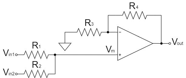
The summing amplifier circuit shown above is the circuit that adds two input voltages and combines the averager circuit with resistor voltage divider and the non-inverting amplifier circuit.
The output voltage $V_m$ of the averager circuit with resistor voltage divider in the 1st stage is:
$$V_m=\frac{R_2V_{in1}+R_1V_{in2}}{R_1+R_2}$$
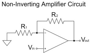
If the input voltage is $V_m$, the output voltage $V_{out}$ of the non-inverting amplifier circuit in the 2nd stage is:
$$V_{out}=\left(1+\frac{R_4}{R_3}\right)V_m$$
$$V_{out}=\left(1+\frac{R_4}{R_3}\right)\left(\frac{R_2V_{in1}+R_1V_{in2}}{R_1+R_2}\right)$$
If $R_3=R_4$, it will be the non-inverting amplifier with an amplification factor of 2x, and if $R_1=R_2$, it will be the simple average value calculation, resulting in the equation that adds $V_{in1}$ and $V_{in2}$.
$$V_{out}=2\left(\frac{V_{in1}+V_{in2}}{2}\right)=V_{in1}+V_{in2}$$
However, in the summing amplifier circuit that applies the non-inverting amplifier circuit, if the signal sources to which the input voltage is applied are separate, the signal sources will interfere with each other, causing the input voltage to fluctuate.
In the summing amplifier circuit that applies the inverting amplifier circuit, each signal source can be considered to be connected to GND by the virtual short, so there is no interference between the signal sources.
Another disadvantage of the summing amplifier circuit that applies the non-inverting amplifier circuit is that the calculation becomes more complex as the number of inputs is increased.
Therefore, most practical summing amplifier circuits will use circuits that apply inverting amplifier circuits.
Please refer to the following article for the calculation of the equation for the non-inverting amplifier circuit.
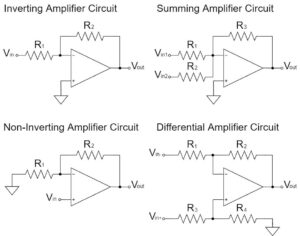
Other Op-Amp Circuit Examples
In this article, the "Op-Amp Summing Amplifier Circuit" has been explained in detail, but there are various other circuits for op-amps as well.
Please refer to the following article for an introduction to the commonly used op-amp circuits.