Op-Amp Non-inverting Amplifier Circuit
In this article, "Op-Amp Non-nverting Amplifier Circuit" will be explained in detail.
The non-inverting amplifier circuit, like the inverting amplifier circuit, is one of the basic circuits in an op-amp.
Op-Amp Non-inverting Amplifier Characteristics
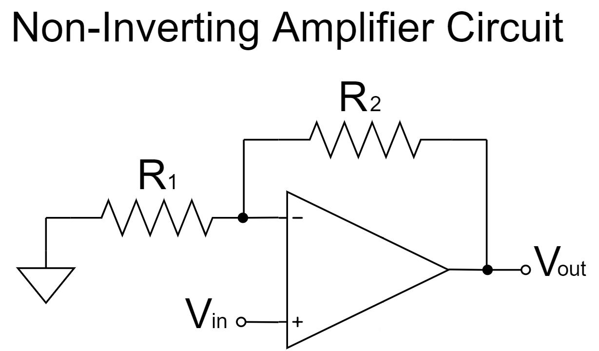
Non-inverting Amplifier Circuit
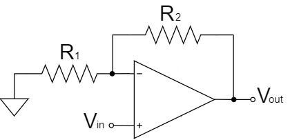
$$V_{out}=\left(1+\frac{R_2}{R_1}\right)V_{in}$$
As shown in the equation above, the non-inverting amplifier circuit amplifies $V_{in}$ by a factor of $1+\frac{R_2}{R_1}$ and outputs it to $V_{out}$.
For example, if $R_1=1kΩ, R_2=10kΩ, V_{in}=1V$;
$$V_{out}=\left(1+\frac{10k}{1k}\right) \times 1=11[V]$$
- Output signal is input signal non-inverted
- Amplification factor is more than 1x
- Electrically unstable in operation
- Very high input impedance
- Output impedance is almost 0
Output signal is input signal non-inverted
In the op-amp non-inverting amplifier circuit, the phase of the input and output signals are the same because the output signal is non-inverted of the input signal.
For example, if the input voltage is +, the output voltage will be +, and if the input voltage is -, the output voltage will be -.
Amplification factor is more than 1x
Since the ratio of the op-amp non-inverting amplification circuit is $1+\frac{R_2}{R_1}$, the amplification factor is always more than one times.
However, by setting the resistor $R_1$ to open (∞Ω) and $R_2$ to short (0Ω), a voltage follower (a buffer with an amplification factor of 1x) can be designed.
Electrically unstable in operation
The op-amp non-inverting amplifier circuit is electrically unstable in operation when compared to the op-amp inverting amplifier circuit.
In an op-amp, the $+$ and $-$ pins are virtually shorted inside the op-amp.
In the case of the op-amp non-inverting amplifier circuit, the operating point is swung by the voltage input to the $+$ pin, and the $-$ pin connected through a virtual short circuit is similarly affected.
Therefore, the operating point is swung by the input voltage, which may cause unstable operation when the input signal is high frequency.
Very high input impedance
The op-amp non-inverting amplifier circuit has a very high input impedance because the input voltage is directly input to the $+$ pin.
(In general, both the $+$ and $-$ input pins of an op-amp have very high input impedance.)
Therefore, even if the impedance of the circuit connected to the input of the op-amp non-inverting amplifier circuit is somewhat high, the voltage drop will not occur with little effect. It is suitable for high-precision measurements.
Output impedance is almost 0
The output impedance of the op-amp non-inverting amplifier circuit is kept at a voltage that satisfies the equation $V_{out}=\left(1+\frac{R_2}{R_1}\right)V_{in}$ by the negative feedback, so it is almost 0.
Therefore, it is almost unaffected by the input impedance of the circuit connected to the output pin of the op-amp, and the required signal level can be extracted without causing a voltage drop.
Op-Amp Non-inverting Amplifier Equations(Formulas)
To obtain the equation for the op-amp non-inverting amplifier circuit, a calculation is made from the equation for the voltage of each part of the circuit and the ideal op-amp is replaced by the nullor model.
Equation Example 1
Op-Amp Schematic Symbol
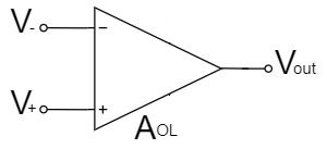
The op-amp amplifies the potential difference between the two input voltages, $V_+$ and $V_-$, with an open-loop gain $A_{OL}$.
$$V_{out}=A_{OL}(V_+-V_-)$$
Non-inverting Amplifier Circuit
In the case of the op-amp non-inverting amplifier circuit, $V_+$ and $V_{in}$ are the same.
$$V_+=V_{in}$$
As a result of the above, $V_{out}$ is:
$$V_{out}=A_{OL}(V_{in}-V_-)\cdots(1)$$
Also, since the $-$ pin of the inverting amplifier circuit has high input impedance and no current can flow through it, the circuit can be represented as shown below:
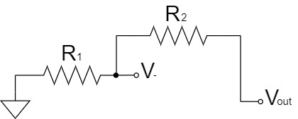
Furthermore, the voltage divider circuit can be changed for clarity as shown below:
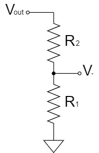
Thus, $V_-$ is:
$$V_-=\frac{R_1}{R_1+R_2}V_{out}\cdots(2)$$
By substituting Eq.(2) into Eq.(1), $V_{out}$ is:
$$V_{out}=A_{OL}\left(V_{in}-\frac{R_1}{R_1+R_2}V_{out}\right)$$
$$V_{out}=A_{OL}V_{in}-\frac{R_1}{R_1+R_2}A_{OL}V_{out}$$
$$V_{out}+\frac{R_1}{R_1+R_2}A_{OL}V_{out}=A_{OL}V_{in}$$
$$\frac{R_1+R_2}{R_1+R_2}V_{out}+\frac{A_{OL}R_1}{R_1+R_2}V_{out}=A_{OL}V_{in}$$
$$\frac{R_1+R_2+A_{OL}R_1}{R_1+R_2}V_{out}=A_{OL}V_{in}$$
$$V_{out}=\frac{R_1+R_2}{R_1+R_2+A_{OL}R_1}A_{OL}V_{in}$$
$$V_{out}=\left(\frac{R_1+R_2}{\frac{R_1+R_2+A_{OL}R_1}{A_{OL}}}\right)V_{in}$$
$$V_{out}=\left(\frac{1}{\frac{R_1+R_2+A_{OL}R_1}{A_{OL}(R_1+R_2)}}\right)V_{in}$$
$$V_{out}=\left(\frac{1}{\frac{A_{OL}R_1}{A_{OL}(R_1+R_2)}+\frac{R_1+R_2}{A_{OL}(R_1+R_2)}}\right)V_{in}$$
$$V_{out}=\left(\frac{1}{\frac{R_1}{R_1+R_2}+\frac{1}{A_{OL}}}\right)V_{in}$$
Given that $A_{OL}$ is an extremely large value (∞), $\frac{1}{A_{OL}}⇒0$:
$$V_{out}=\left(\frac{1}{\frac{R_1}{R_1+R_2}}\right)V_{in}$$
$$V_{out}=\frac{R_1+R_2}{R_1}V_{in}$$
$$V_{out}=\left(1+\frac{R_2}{R_1}\right)V_{in}$$
Equation Example 2
Non-inverting Amplifier Circuit
In the case of the op-amp non-inverting amplifier circuit, $V_+$ and $V_{in}$ are the same.
$$V_+=V_{in}$$
Furthermore, the $+$ and $-$ pins can be considered to be connected through a virtual short.
$$V_-=V_+=V_{in}\cdots(1)$$
Also, since the $-$ pin of the inverting amplifier circuit has high input impedance and no current can flow through it, the circuit can be represented as shown below:
Furthermore, the voltage divider circuit can be changed for clarity as shown below:
Thus, $V_-$ is:
$$V_-=\frac{R_1}{R_1+R_2}V_{out}\cdots(2)$$
By substituting Eq.(2) into Eq.(1), $V_{out}$ is:
$$V_{in}=\frac{R_1}{R_1+R_2}V_{out}$$
$$\frac{R_1}{R_1+R_2}V_{out}=V_{in}$$
$$V_{out}=\frac{R_1+R_2}{R_1}V_{in}$$
$$V_{out}=\left(1+\frac{R_2}{R_1}\right)V_{in}$$
Equation Example 3(Using Nullor Model)
Non-inverting Amplifier Circuit
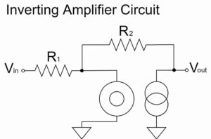
We replace the ideal op-amp with the nullor model and calculate the non-inverting amplifier circuit as shown below:
The nullor model can represent a virtual short in an op amp, which simplifies the calculation.
For a more detailed explanation of the nullor model, please refer to the following article.
Non-inverting Amplifier Circuit(Nullor Model)
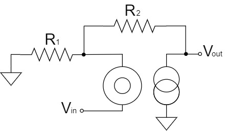
We will try to change the above schematic for clarity.
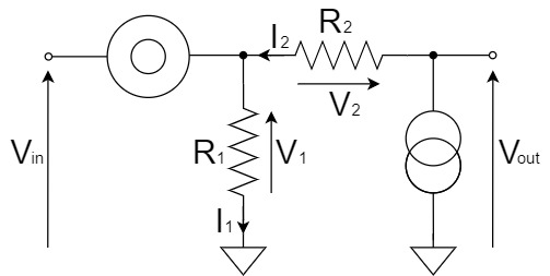
From Kirchhoff's Voltage Law(KVL), the relation between $V_{out}$, $V_1$ and $V_2$ is:
$$V_{out}=V_1+V_2$$
Therefore, we will obtain $V_1$ and $V_2$, respectively. First, $V_1$ is:
$$V_1=V_{in}\cdots(1)$$
Next, from Kirchhoff's Current Law(KCL), $I_2=I_1$, so $V_2$ is:
$$V_2=R_2I_2=R_2I_1$$
Since $I_1$ is obtained as shown below:
$$I_1=\frac{V_1}{R_1}=\frac{V_{in}}{R_1}$$
Therefore, $V_2$ is:
$$V_2=R_2I_2=R_2I_1=\frac{R_2}{R_1}V_{in}\cdots(2)$$
By substituting Eq.(1) and Eq.(2) into $V_{out}=V_1+V_2$, the equation for the non-inverting amplifier circuit is:
$$V_{out}=V_1+V_2=V_{in}+\frac{R_2}{R_1}V_{in}$$
$$V_{out}=\left(1+\frac{R_2}{R_1}\right)V_{in}$$
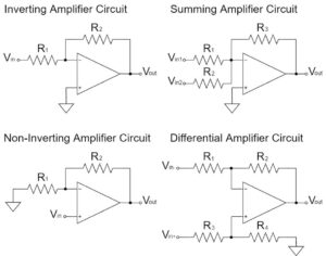
Other Op-Amp Circuit Examples
In this article, the "Op-Amp Non-inverting Amplifier Circuit" has been explained in detail, but there are various other circuits for op-amps as well.
Please refer to the following article for an introduction to the commonly used op-amp circuits.