Op-Amp Circuit Examples
In this article, "relatively commonly used op-amp circuits" will be introduced.
For more detailed explanations of each circuit, please refer to the linked articles.
Amplifier Circuits
An amplifier circuit is a circuit used to change a small signal into a large signal.
The op-amp amplifer circuit can be easily set by the value of two resistors, and the gain can be designed to be much higher than that of a transistor.
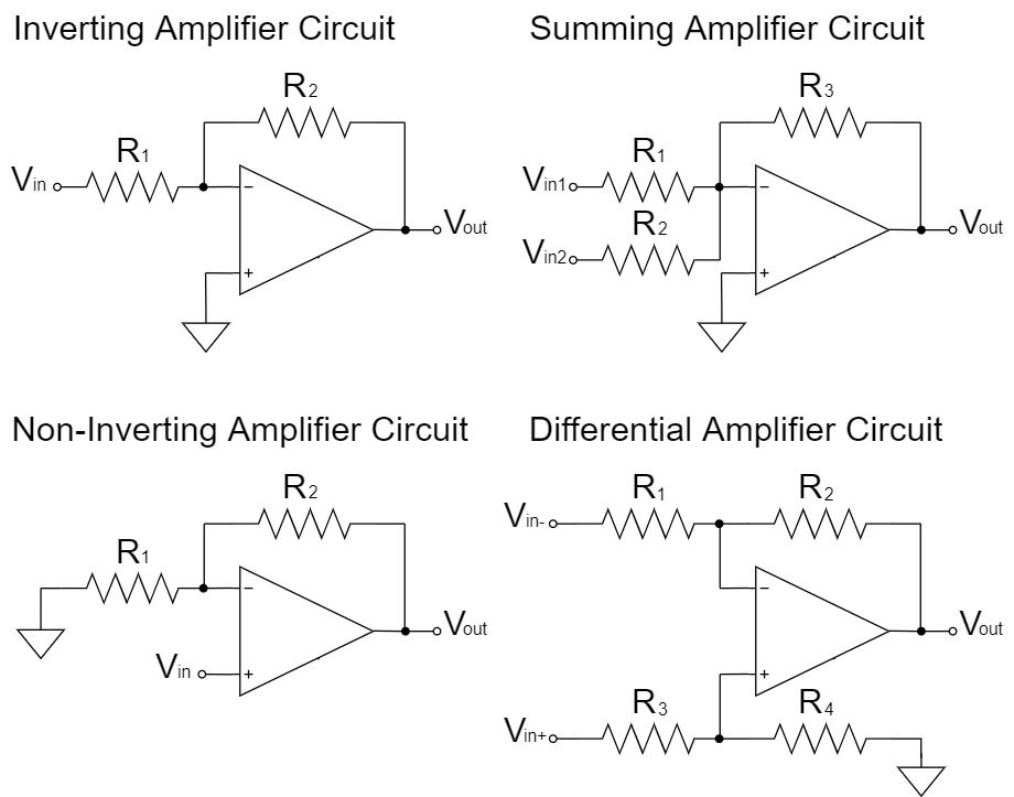
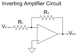
Inverting Amplifier Circuit
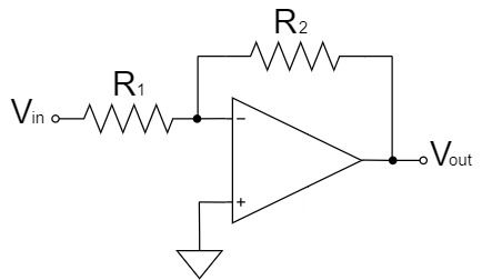
$$V_{out}=-\frac{R_2}{R_1}V_{in}$$
As shown in the equation above, the inverting amplifier circuit amplifies $V_{in}$ by a factor of $\frac{R_2}{R_1}$ and outputs it to $V_{out}$.
Also, the $V_{out}$ signal is inverted, as indicated by the "$-$" polarity.
For example, if $R_1=1kΩ, R_2=10kΩ, V_{in}=1V$;
$$V_{out}=-\frac{10k}{1k} \times 1=-10[V]$$
For a more detailed description of the op-amp inverting amplifier circuit, please refer to the following article.
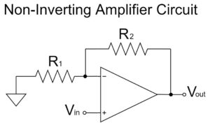
Non-inverting Amplifier Circuit
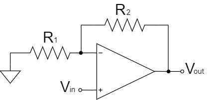
$$V_{out}=\left(1+\frac{R_2}{R_1}\right)V_{in}$$
As shown in the equation above, the non-inverting amplifier circuit amplifies $V_{in}$ by a factor of $1+\frac{R_2}{R_1}$ and outputs it to $V_{out}$.
For example, if $R_1=1kΩ, R_2=10kΩ, V_{in}=1V$;
$$V_{out}=\left(1+\frac{10k}{1k}\right) \times 1=11[V]$$
For a more detailed description of the op-amp non-inverting amplifier circuit, please refer to the following article.
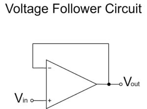
Voltage Follower Circuit
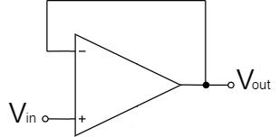
$$V_{out}=V_{in}$$
As shown in the equation above, the voltage follower circuit is amplified by a factor of 1x and the $V_{in}$ signal is output directly to $V_{out}$.
Since the non-inverting amplifier circuit cannot build a circuit with an amplification factor of 1x, the voltage follower is used instead.
For example, if $V_{in}=1V$;
$$V_{out}=1[V]$$
For a more detailed description of the op-amp voltage follower circuit, please refer to the following article.
Arithmetic Circuits
An arithmetic circuit is a circuit used to calculate the addition, subtraction, etc. of multiple signals.
The op-amp arithmetic circuit can be designed more easily than that of a transistor because it can be made by modifying a part of the op-amp inverting amplifier circuit, etc.
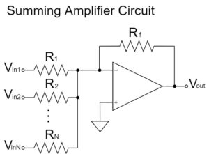
Summing Amplifier Circuit
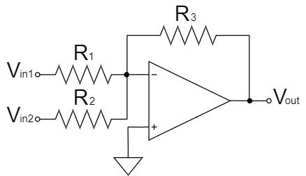
$$V_{out}=-R_3\left(\frac{V_{in1}}{R_1}+\frac{V_{in2}}{R_2}\right)$$
The summing amplifier circuit is a circuit with an additional resistor added in parallel to the input side of the inverting amplifier circuit.
As shown in the above equation, multiple input signals are added and output.
If weighting by resistance ratio is not necessary, the added voltage of the input signals by setting $R_1=R_2=R_3$ is inverted and output.
For example, if $R_1=R_2=R_3=10kΩ, V_{in1}=3V, V_{in2}=7V$;
$$V_{out}=-10k\left(\frac{3}{10k}+\frac{7}{10k}\right)=-10[V]$$
For a more detailed description of the op-amp summing amplifier circuit, please refer to the following article.
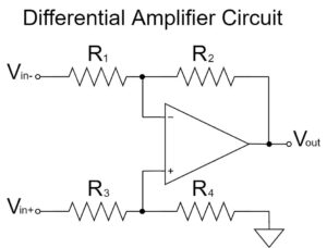
Differential Amplifier Circuit
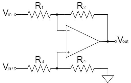
$$V_{out}=\frac{R_2}{R_1}\left(V_{in+}-V_{in-}\right)$$
The differential amplifier circuit amplifies the difference between two input signals.
As shown in the equation above, if $R_1=R_3, R_2=R_4$, then the signal $V_{in+}-V_{in-}$ is amplified and output to $V_{out}$ with an amplification factor of $\frac{R_2}{R_1}$.
For example, if $R_1=R_2=R_3=R_4=10kΩ, V_{in+}=12V, V_{in-}=2V$;
$$V_{out}=\frac{10k}{10k}\left(12-2\right)=10[V]$$
For a more detailed description of the op-amp differential amplifier circuit, please refer to the following article.
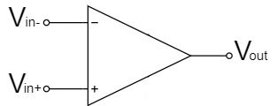
Comparator Circuit
$$V_{out}=+V_{CC} \quad (V_{in+}>V_{in-})$$
$$V_{out}=-V_{CC} \quad (V_{in+} \lt V_{in-})$$
The comparator circuit is operated in open loop without negative feedback.
The output is determined according to the relationship between the non-inverting input $V_{in+}$ and the inverting input $V_{in-}$.
As shown in the above equation, when $V_{in+}>V_{in-}$, the output saturates at the + side supply voltage $+V_{CC}$, and when $V_{in+} \lt V_{in-}$, it saturates at the - side supply voltage $-V_{CC}$.
However, in practice, the most common use is to provide a reference voltage to one input and compare the voltage applied to the other input.
There are circuits that use either inverting or non-inverting inputs for the reference voltage as shown below:
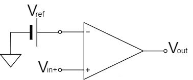
$$V_{out}=+V_{CC} \quad (V_{in+}>V_{ref})$$
$$V_{out}=-V_{CC} \quad (V_{in+} \lt V_{ref})$$
First, as shown in the above equation, if the reference voltage is an inverting input, when $V_{in+}>V_{ref}$, the output saturates at the + side supply voltage $+V_{CC}$, and when $V_{in+} \lt V_{ref}$, it saturates at the - side supply voltage $-V_{CC}$.
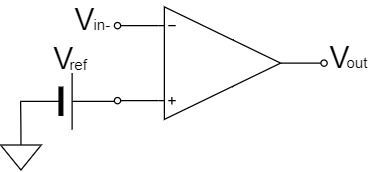
$$V_{out}=-V_{CC} \quad (V_{in-}>V_{ref})$$
$$V_{out}=+V_{CC} \quad (V_{in-} \lt V_{ref})$$
Next, as shown in the above equation, if the reference voltage is a non-inverting input, when $V_{in-}>V_{ref}$, the output saturates at the + side supply voltage $-V_{CC}$, and when $V_{in-} \lt V_{ref}$, it saturates at the - side supply voltage $+V_{CC}$.
Integrator Circuit
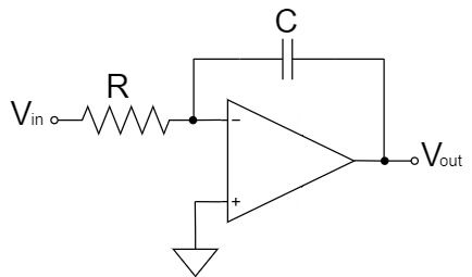
$$V_{out}=-\frac{1}{CR} \int V_{in}dt$$
The integrator circuit is a circuit in which the feedback resistor of the inverting amplifier circuit is replaced by a capacitor.
As shown in the equation above, the integrator circuit amplifies the integral value of $V_{in}$. by a factor of $\frac{1}{CR}$ and outputs it to $V_{out}$.
Also, the $V_{out}$ signal is inverted, as indicated by the "$-$" polarity.
Therefore, the output voltage of the integrator circuit increases in proportion to the passage of time, but the output saturates at the upper supply voltage limit of the op-amp voltage.
Differentiator Circuit
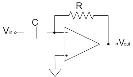
$$V_{out}=-CR\frac{dV_{in}}{dt}$$
A differentiator circuit is a circuit in which the resistor on the input side of the inverting amplifier circuit is replaced by a capacitor.
As shown in the equation above, the differentiator circuit amplifies the differential value of $V_{in}$. by a factor of $CR$ and outputs it to $V_{out}$.
Also, the $V_{out}$ signal is inverted, as indicated by the "$-$" polarity.
Therefore, if $V_{in}$ is unchanged and constant, $V_{out}$ remains at $0V$, and if $V_{in}$ changes significantly, a voltage proportional to that slope is output to $V_{out}$.
For example, if a triangle wave is input to a differentiator circuit, a square wave is output. If the slope of the triangle wave is large, it saturates at the supply voltage, similar to an integrator circuit.