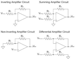
Op-Amp Differential Amplifier Circuit
In this article, "Op-Amp Differential Amplifier Circuit" will be explained in detail.
The differential amplifier circuit amplifies the difference between input voltages.
Voltage Subtractor Circuit
Op-Amp Differential Amplifier Characteristics
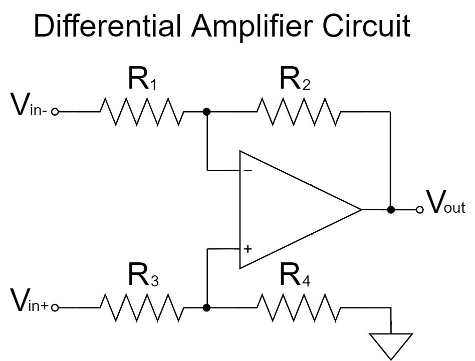
Differential Amplifier Circuit
$$V_{out}=\frac{R_2}{R_1}\left(V_{in+}-V_{in-}\right)$$
The differential amplifier circuit amplifies the difference between two input signals.
As shown in the equation above, if $R_1=R_3, R_2=R_4$, then the signal $V_{in+}-V_{in-}$ is amplified and output to $V_{out}$ with an amplification factor of $\frac{R_2}{R_1}$.
For example, if $R_1=R_2=R_3=R_4=10kΩ, V_{in+}=12V, V_{in-}=2V$;
$$V_{out}=\frac{10k}{10k}\left(12-2\right)=10[V]$$
Therefore, even if the GND levels of the input signal source and the differential amplifier circuit are different, the difference between two input voltages can be amplified without problems and output at the GND level of the differential amplifier circuit.
However, if the tolerance in the resistor is too large, the common-mode input voltage will not be sufficiently removed.
In addition to using op-amps with high CMRR (common-mode rejection ratio), it is necessary to balance the resistance ratio ($R_2/R_1=R_4/R_3$) using high-precision or variable resistors to further remove common-mode voltage.
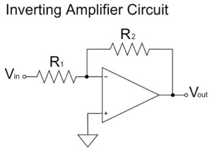
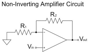
Since the differential amplifier circuit is a combination of the inverting amplifier circuit and the non-inverting amplifier circuit, so it is better to understand these two circuits first.
Please refer to the following article for the calculation of the equation for the inverting amplifier circuit and the non-inverting amplifier circuit.
Op-Amp Differential Amplifier Equations(Formulas)
To obtain the equation for the op-amp differential amplifier circuit, a calculation is made from the equation for the voltages of each part of the circuit.
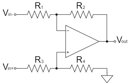
Differential Amplifier Circuit
The $+$ and $-$ pins can be connected through a virtual short.
$$V_-=V_+\cdots(1)$$
Therefore, $V_+$ and $V_-$, which are the terminal voltages of the op-amp, are obtained and $V_{out}$ is calculated.
First, $V_+$ is obtained. Since $V_+$ is the voltage divided by $V_{in+}$ with $R_3$ and $R_4$, the voltage divider circuit is as shown below:
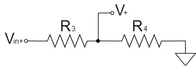
Furthermore, the voltage divider circuit can be changed for clarity as shown below:
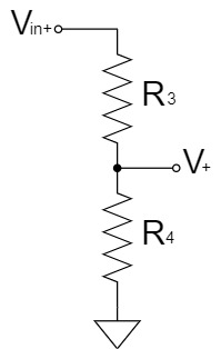
Thus, $V_+$ is:
$$V_+=\frac{R_4}{R_3+R_4}V_{in+}\cdots(2)$$
Next, $V_-$ is obtained. The $-$ pin of the differential amplifier circuit has a high input impedance, so no current can flow through it, resulting as shown below:
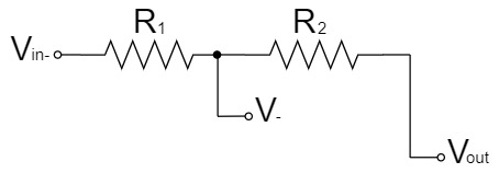
By the superposition theorem, $V_-$ can be easily obtained as a voltage divider circuit by dividing the above circuit into two parts.
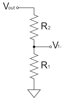
$$V_{1-}=\frac{R_1}{R_1+R_2}V_{out}$$

$$V_{2-}=\frac{R_2}{R_1+R_2}V_{in-}$$
Thus, $V_-$ is:
$$V_{-}=V_{1-}+V_{2-}$$
$$V_-=\frac{R_1}{R_1+R_2}V_{out}+\frac{R_2}{R_1+R_2}V_{in-}\cdots(3)$$
By substituting Eq.(2) and Eq.(3) into Eq.(1), $V_{out}$ is:
$$\frac{R_1}{R_1+R_2}V_{out}+\frac{R_2}{R_1+R_2}V_{in-}=\frac{R_3}{R_3+R_4}V_{in+}$$
$$\frac{R_1}{R_1+R_2}V_{out}=\frac{R_3}{R_3+R_4}V_{in+}-\frac{R_2}{R_1+R_2}V_{in-}$$
$$V_{out}=\frac{R_4(R_1+R_2)}{R_1(R_3+R_4)}V_{in+}-\frac{R_2}{R_1}V_{in-}$$
さらに、$R_1=R_3, R_2=R_4$とすると、$V_{out}$は以下のようになります。
And, if $R_1=R_3, R_2=R_4$, $V_{out}$ is:
$$V_{out}=\frac{R_2(R_1+R_2)}{R_1(R_1+R_2)}V_{in+}-\frac{R_2}{R_1}V_{in-}$$
$$V_{out}=\frac{R_2}{R_1}V_{in+}-\frac{R_2}{R_1}V_{in-}$$
$$V_{out}=\frac{R_2}{R_1}\left(V_{in+}-V_{in-}\right) \quad or \quad V_{out}=-\frac{R_2}{R_1}\left(V_{in-}-V_{in+}\right)$$
Other Op-Amp Circuit Examples
In this article, the "Op-Amp Differential Amplifier Circuit" has been explained in detail, but there are various other circuits for op-amps as well.
Please refer to the following article for an introduction to the commonly used op-amp circuits.