Op-Amp Voltage Follower Circuit
In this article, "Op-Amp Voltage Follower Circuit" will be explained in detail.
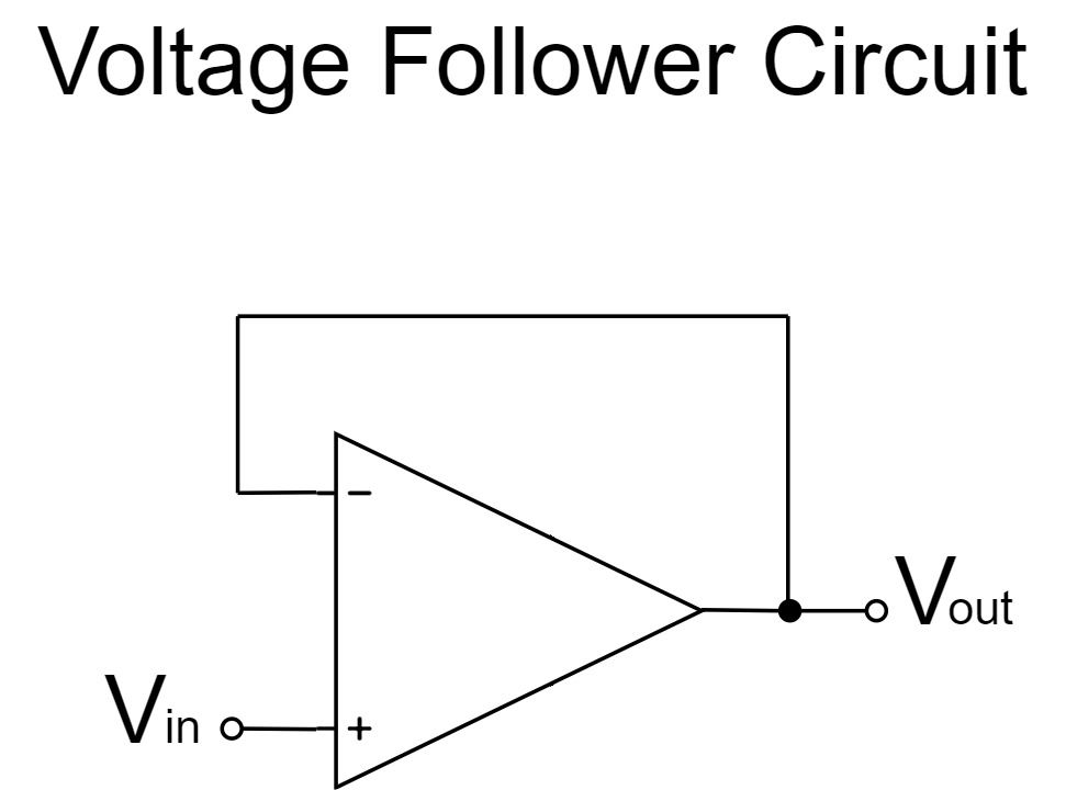
A voltage follower is a simple circuit in which the output pin of an op-amp is connected to the inverting pin (negative feedback). It is often used for impedance conversion or isolation amplifier.
Op-Amp Voltage Follower Characteristics
Voltage Follower Circuit
$$V_{out}=V_{in}$$
As shown in the equation above, the voltage follower circuit is amplified by a factor of 1x and the $V_{in}$ signal is output directly to $V_{out}$.
For example, if $V_{in}=1V$;
$$V_{out}=1[V]$$
In addition, since the voltage follower circuit is the non-inverting amplifier circuit with an amplification factor of 1x, the features of the voltage follower circuit and the non-inverting amplifier circuit are almost the same.
- Output signal is input signal non-inverted
- Amplification factor is 1x
- Electrically unstable in operation
- Very high input impedance
- Output impedance is almost 0
Output signal is input signal non-inverted
In the op-amp voltage follower circuit, the phase of the input and output signals are the same because the output signal is non-inverted of the input signal.
For example, if the input voltage is +, the output voltage will be +, and if the input voltage is -, the output voltage will be -.
Amplification factor is 1x
The voltage follower circuit is amplified by a factor of 1x.
It is often used for "impedance conversion" or "isolation amplifier".
Impedance Conversion
If the output impedance of the Signal Source, such as a sensor, is high and the input impedance of the Load is low, a voltage drop will occur and accurate voltage will not be transmitted to the load side.
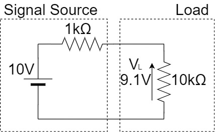
As shown above, if the signal source has a voltage of $10[V]$ and an output impedance of $1[kΩ]$, the load voltage $V_L$ will be as shown below when a $10[kΩ]$ load is connected:
$$V_L=\frac{10kΩ}{1kΩ+10kΩ} \times 10V \fallingdotseq 9.1[V]$$
Thus, the load voltage $V_L$ is about $9.1[V]$, which is an tolerance of nearly 10% compared to the original $10[V]$ voltage.
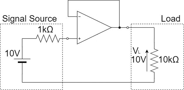
Therefore, as shown above, a voltage follower can be used as a buffer between the signal source and the load, and impedance transformation can be performed to convey accurate voltage.
Since the input impedance of the voltage follower is high and the output impedance of it is low, the $10[V]$ voltage of the signal source can be transmitted directly to the load side without any voltage drop.
Isolation Amplifier
When a load resistor is connected to the voltage divider circuit, the resistance value changes, so that accurate voltage is not transmitted to the load side.
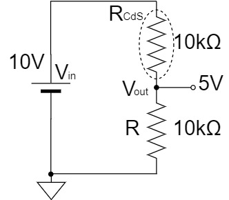
As shown above, the resistance of the CdS (optical sensor) GL5528 changes depending on the incident light, and the resistance value, which is about $1[MΩ]$ in the dark, drops to about $10[kΩ]$ in the light.
(The light resistance of CdS GL5528 ranges from 10~20[kΩ] at 10Lux, but for the sake of clarity, we will assume 10[kΩ].)
Therefore, if the input voltage $V_{in}$ is $10[V]$, the output voltage $V_{out}$ is $5[V]$ when it is light as shown below.
$$V_{out}=\frac{R}{R_{CdS}+R} \times V_{in} = \frac{10kΩ}{10kΩ+10kΩ} \times 10V = 5[V]$$
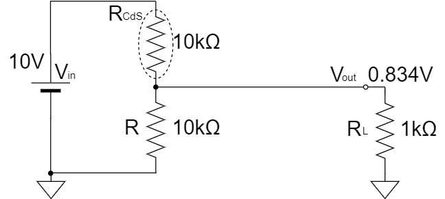
However, when a load resistor $R_{L}$ is connected, the output voltage $V_{out}$ becomes about $0.834[V]$ due to the combined resistance by $R$ and $R_{L}$.
$$R//R_{L}=\frac{R \times R_{L}}{R + R_{L}} = \frac{10k \times 1k}{10k + 1k} \fallingdotseq 0.91[kΩ]$$
$$V_{out}=\frac{R//R_{L}}{R_{CdS}+R//R_{L}} \times V_{in} = \frac{0.91k}{10k+0.91k} \times 10 \fallingdotseq 0.834[V]$$
In other words, it shows a dark state in spite of a light state.
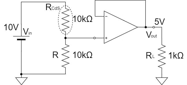
Therefore, as described above, a voltage follower can be connected between the voltage divider circuit and the load resistor to separate the circuits and convey accurate voltage.
Since the input impedance of the voltage follower is high and the output impedance of it is low, the $10[V]$ voltage of the signal source can be transmitted directly to the load side without any voltage drop.
Electrically unstable in operation
The op-amp voltage follower circuit is electrically unstable in operation when compared to the op-amp inverting amplifier circuit.
In an op-amp, the $+$ and $-$ pins are virtually shorted inside the op-amp.
In the case of the op-amp voltage follower circuit, the operating point is swung by the voltage input to the $+$ pin, and the $-$ pin connected through a virtual short circuit is similarly affected.
Therefore, the operating point is swung by the input voltage, which may cause unstable operation when the input signal is high frequency.
Very high input impedance
The op-amp voltage follower circuit has a very high input impedance because the input voltage is directly input to the $+$ pin.
(In general, both the $+$ and $-$ input pins of an op-amp have very high input impedance.)
Therefore, even if the impedance of the circuit connected to the input of the op-amp voltage follower circuit is somewhat high, the voltage drop will not occur with little effect. It is suitable for high-precision measurements.
Output impedance is almost 0
The output impedance of the op-amp voltage follower circuit is kept at a voltage that satisfies the equation $V_{out}=V_{in}$ by the negative feedback, so it is almost zero.
Therefore, it is almost unaffected by the input impedance of the circuit connected to the output pin of the op-amp, and the required signal level can be extracted without causing a voltage drop.
Op-Amp Voltage Follower Equations(Formulas)
To obtain the equation for the op-amp voltage follower circuit, "Calculations from negative feedback and virtual short circuit" and "Calculations from non-inverting amplifier circuit" are used.
Equation Example 1(from Negative Feedback and Virtual Short)
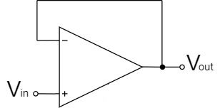
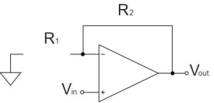
Voltage Follower Circuit
In the case of the voltage follower circuit, $V_{out}$ and $V_-$ are directly connected to apply negative feedback, as shown below:
$$V_{out}=V_-$$
Also, $V_+$ and $V_{in}$ are the same for the voltage follower circuit:
$$V_+=V_{in}$$
Furthermore, the $+$ and $-$ pins are connected virtually inside the op-amp.
$$V_+=V_-$$
Therefore, $V_{out}$ of the voltage follower circuit is:
$$V_{out}=V_{in}$$
Equation Example 2(from Non-inverting Amplifier Circuit)
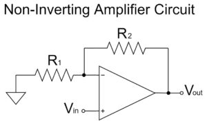
Non-inverting Amplifier Circuit
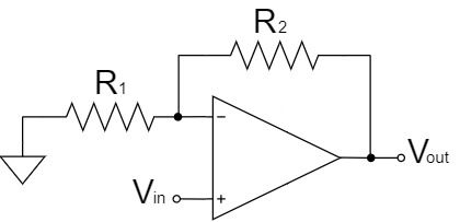
The voltage follower can be a circuit with the resistor $R_1$ of the non-inverting amplifier circuit is open (∞Ω) and $R_2$ of it is short (0Ω).
Therefore, the equation for the voltage follower circuit can be calculated from the equation for the non-inverting amplifier circuit as shown below:
$$V_{out}=\left(1+\frac{R_2}{R_1}\right)V_{in}=\left(1+\frac{0}{∞}\right)V_{in}$$
$$V_{out}=V_{in}$$
Please refer to the following article for the calculation of the equation for the non-inverting amplifier circuit.
Other Op-Amp Circuit Examples
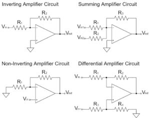
In this article, the "Op-Amp Voltage Follower Circuit" has been explained in detail, but there are various other circuits for op-amps as well.
Please refer to the following article for an introduction to the commonly used op-amp circuits.