LTspice-Types of Voltage and Current Sources
This article introduces the various types of voltage and current sources available in LTspice.
Independent Voltage and Curent Sources
- Voltage Source: voltage, cell, signal
- Current Source: current
Voltage Source
The independent voltage source can output a set voltage. It is the most frequently used basic voltage source.
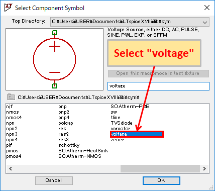
To use an independent voltage source, click on "Component" in the toolbar and select "voltage" when creating the schematic.
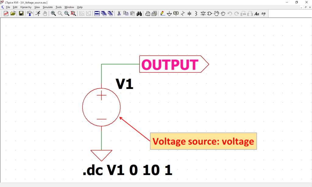
To check the operation of an independent voltage source, we will create the above circuit. The simulation will perform a DC sweep analysis and increase the voltage source by 1V from 0 to 10V.
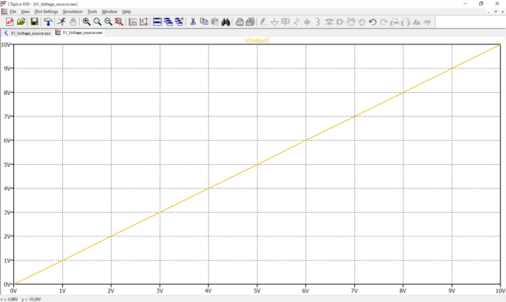
After the simulation, if you check the voltage waveform of V(OUTPUT), you will see that the voltage is increasing by 1V from 0 to 10V as you have set.
When setting a signal source for an independent voltage source, right-clicking on a component in the schematic with the mouse brings up the following setting screen, where you can enter a DC voltage value in the "DC value[V]".
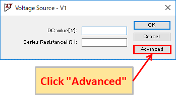
Also, clicking "Advanced" opens the "Independent Voltage Source" screen for more detailed signal source settings.
Please refer to the following article for detailed signal source settings.
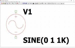
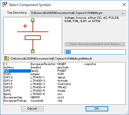
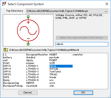
The "cell" and "signal" parts models only have different schematic symbols, so they can be used as independent voltage sources in the same way as "voltage".
However, it would be difficult to understand if they are used interchangeably in the same application in the schematic, so it would be better to distinguish between "signal" as the main signal source, "voltage" as a sub signal source, "cell" as a normal power supply, and so on, by dividing them into different applications.
The schematic used in this simulation of an independent voltage source can be downloaded from the link below.
Current Source
The independent current source can output a set voltage.
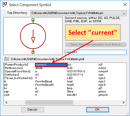
To use an independent current source, click on "Component" in the toolbar and select "current" when creating the schematic.
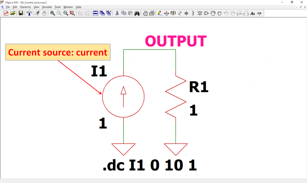
To check the operation of an independent current source, we will create the above circuit. The simulation will perform a DC sweep analysis and increase the current source by 1A from 0 to 10A.

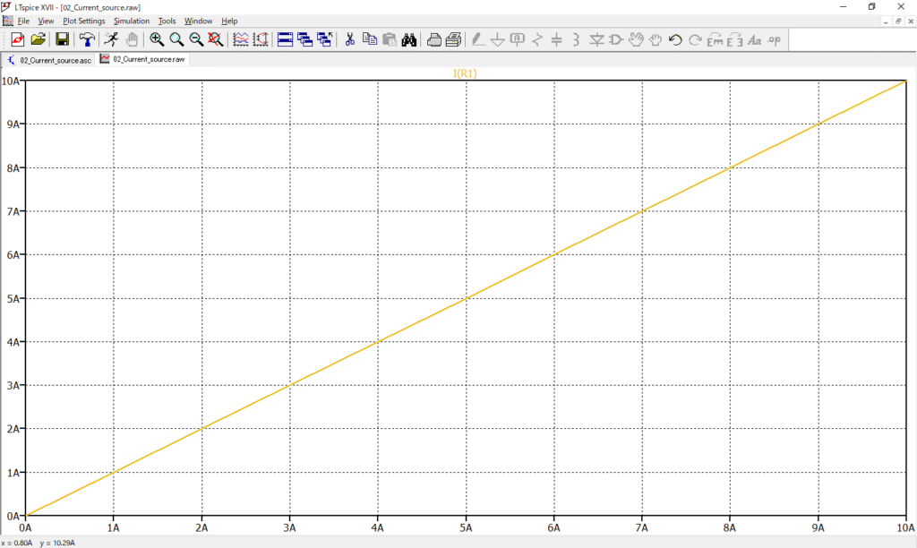
After the simulation, if you check the current waveform of I(R1), you will see that the current is increasing by 1A from 0 to 10A as you have set.
When setting a signal source for an independent current source, right-clicking on a component in the schematic with the mouse brings up the following setting screen, where you can enter a DC current value in the "DC value[A]".
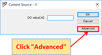
Also, clicking "Advanced" opens the "Independent Current Source" screen for more detailed signal source settings. It is basically the same as setting up an independent voltage source.
Please refer to the following article for detailed signal source settings.

The schematic used in this simulation of an independent current source can be downloaded from the link below.
Controlled Voltage and Curent Sources
- Voltage Dependent Voltage Source: e
- Voltage Dependent Current Source: g
- Linear Current Dependent Current Source: f
- Linear Current Dependent Voltage Source: h
Voltage Dependent Voltage Source
The voltage dependent voltage source consists of two input terminals on the left side and two output terminals on the right side.
By inputting a voltage to the input terminal, a voltage proportional to the input voltage can be output from the output terminal.
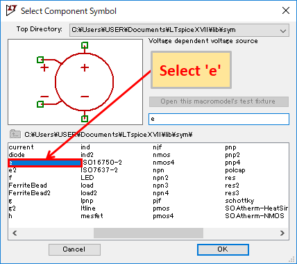
To use a voltage dependent voltage source, click on "Component" in the toolbar and select 'e' when creating the schematic.
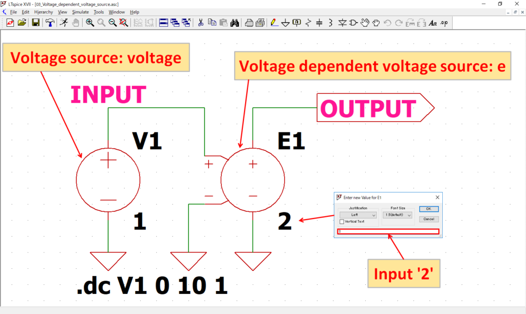
To check the operation of a voltage dependent voltage source, we will create the above circuit.
To set the voltage dependent voltage source, right-click on the 'E' with the mouse and enter '2' as the amplification factor.
The simulation will perform a DC sweep analysis and increase the voltage source by 1V from 0 to 10V.

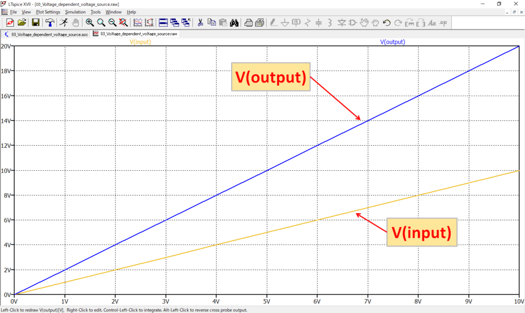
After the simulation, if you check the voltage waveforms of V(input) and V(output), you can see that V(output) is output at twice the voltage of V(input).
The schematic used in this simulation of a voltage dependent voltage source can be downloaded from the link below.
Voltage Dependent Current Source
The voltage dependent current source consists of two input terminals on the left side and two output terminals on the right side.
By inputting a voltage to the input terminal, a current proportional to the input voltage can be output from the output terminal.
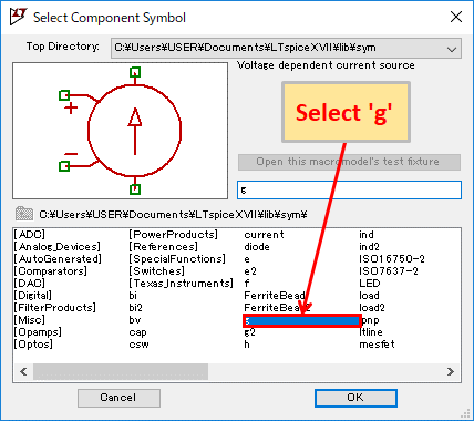
To use a voltage dependent current source, click on "Component" in the toolbar and select 'g' when creating the schematic.
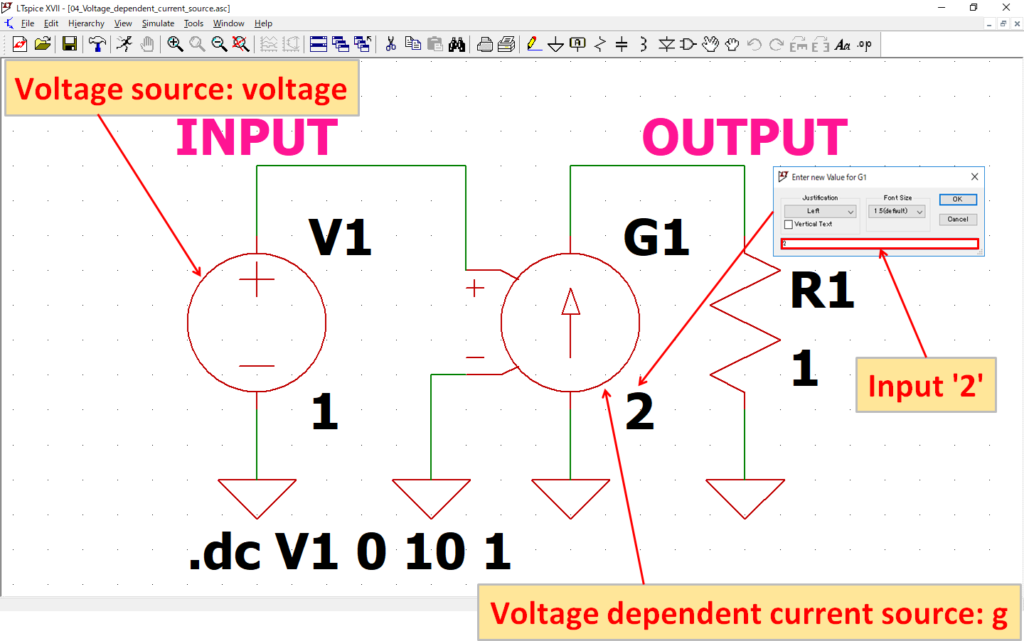
To check the operation of a voltage dependent current source, we will create the above circuit.
To set the voltage dependent current source, right-click on the 'G' with the mouse and enter '2' as the amplification factor.
The simulation will perform a DC sweep analysis and increase the voltage source by 1V from 0 to 10V.

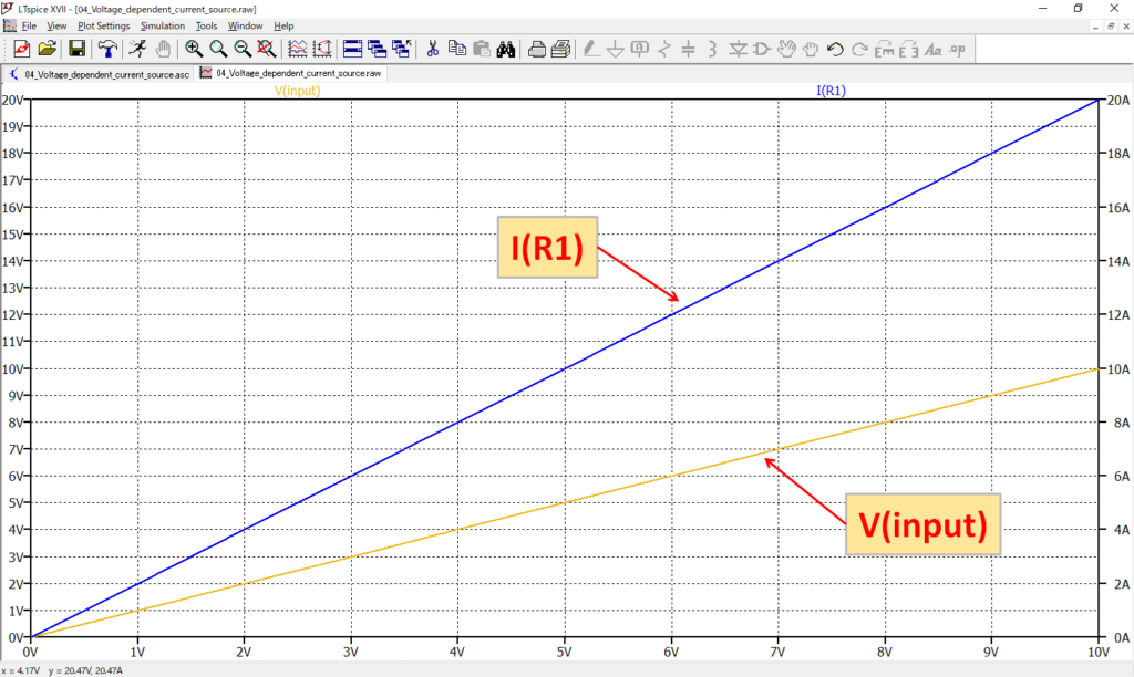
After the simulation, if you check the voltage and current waveforms of V(input) and I(R1), you can see that I(R1) is output at twice the voltage of V(input).
The schematic used in this simulation of a voltage dependent current source can be downloaded from the link below.
Linear Current Dependent Current Source
The linear current dependent current source can output a current proportional to the detected current.
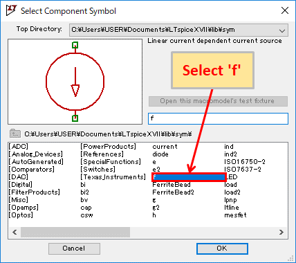
To use a linear current dependent current source, click on "Component" in the toolbar and select 'f' when creating the schematic.
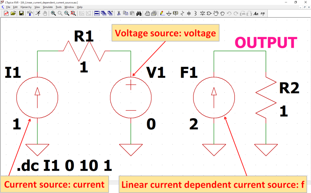
To check the operation of a linear current dependent current source, we will create the above circuit.
The voltage source V1 can be used as an ammeter by setting the DC value[V] to '0'.
The simulation will perform a DC sweep analysis and increase the current source I1 by 1A from 0 to 10A. The current is detected by the voltage source V1 used as an ammeter.

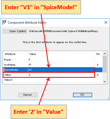
To set the linear current dependent current source, right-click with the mouse on the schematic symbol and enter "V1" in "SpiceModel" as the voltage source to detect the current and '2' in "Value" as the amplification factor.
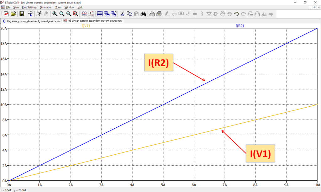
After the simulation, if you check the current waveforms of I(V1) and I(R2), you can see that I(R2) is output at twice the current of I(V1).
The schematic used in this simulation of a linear current dependent current source can be downloaded from the link below.
Linear Current Dependent Voltage Source
The linear current dependent voltage source can output a voltage proportional to the detected current.
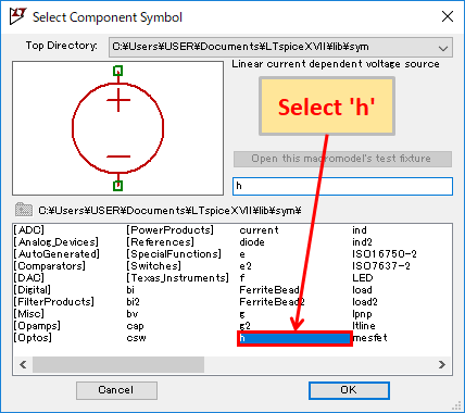
To use a linear current dependent voltage source, click on "Component" in the toolbar and select 'h' when creating the schematic.
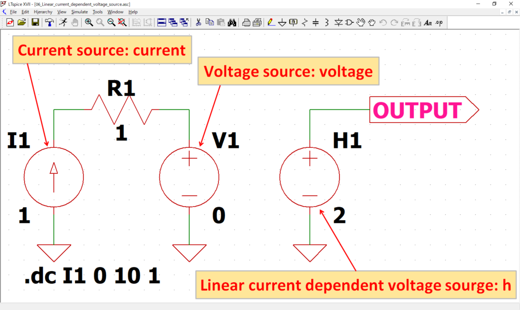
To check the operation of a linear current dependent voltage source, we will create the above circuit.
The simulation will perform a DC sweep analysis and increase the current source I1 by 1A from 0 to 10A. The current is detected by the voltage source V1 used as an ammeter.

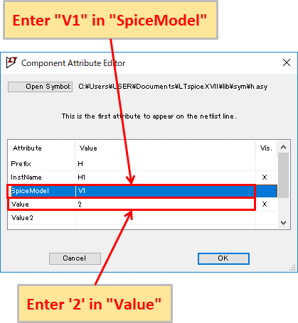
To set the linear current dependent voltage source, right-click with the mouse on the schematic symbol and enter "V1" in "SpiceModel" as the voltage source to detect the current and '2' in "Value" as the amplification factor.
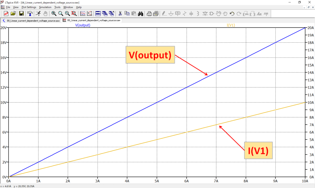
After the simulation, if you check the current and voltage waveforms of I(V1) and V(output), you can see that V(output) is output at twice the voltage of I(V1).
The schematic used in this simulation of a linear current dependent voltage source can be downloaded from the link below.
Behavioral Voltage and Curent Sources
- Arbitrary Behavioral Voltage Source: bv
- Arbitrary Behavioral Current Source: bi
Arbitrary Behavioral Voltage Source
The arbitrary behavioral voltage source can synthesize and output multiple input voltages.
Voltage sources, functions, and arithmetic operators can be synthesized to create complex signals.
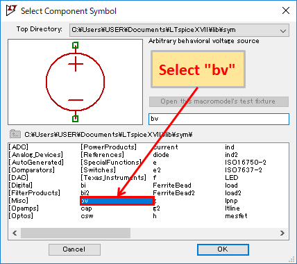
To use a arbitrary behavioral voltage source, click on "Component" in the toolbar and select "bv" when creating the schematic.
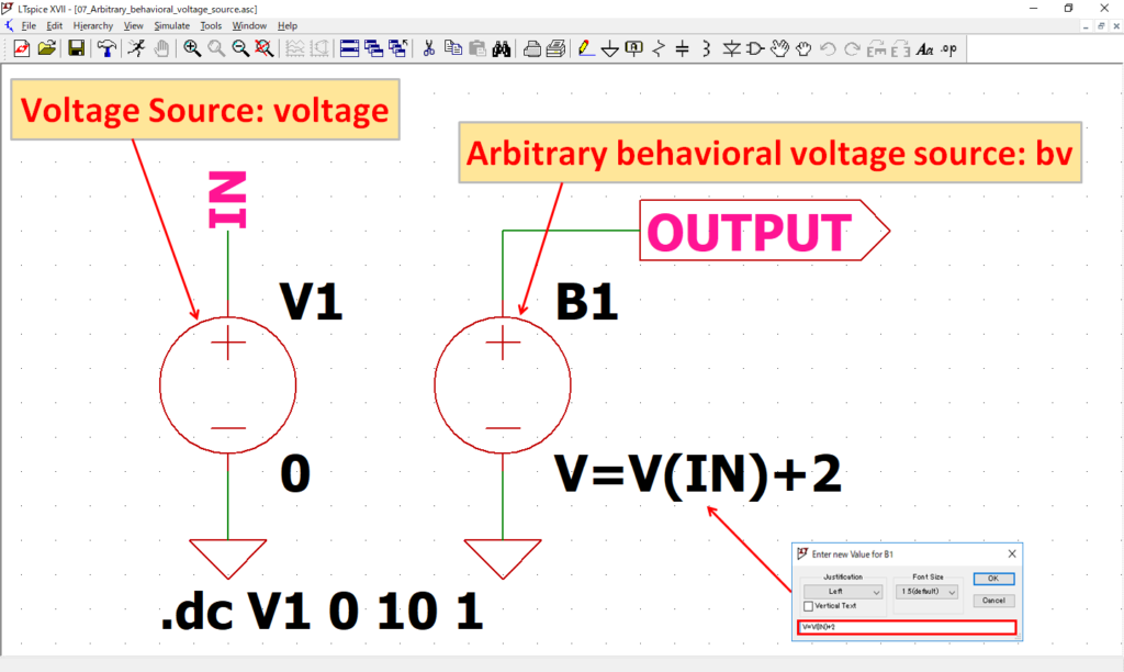
To check the operation of a arbitrary behavioral voltage source, we will create the above circuit.
To set the arbitrary behavioral voltage source, right-click on "V=F(…)" with the mouse and enter "V=V(IN)+2". Now the voltage obtained by adding 2V to V(IN) will be the output of the arbitrary behavioral voltage source.
The simulation will perform a DC sweep analysis and increase the voltage source V1 by 1V from 0 to 10V.

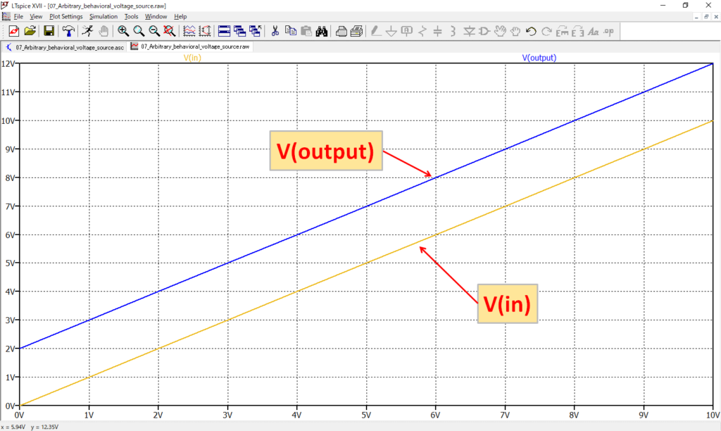
After the simulation, if you check the voltage waveforms of V(in) and V(output), you can see that V(output) is output at a voltage equal to V(in) plus 2V.
The schematic used in this simulation of a arbitrary behavioral voltage source can be downloaded from the link below.
Arbitrary Behavioral Current Source
The arbitrary behavioral current source can synthesize and output multiple input currents.
Voltage sources, functions, and arithmetic operators can be synthesized to create complex signals.
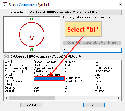
To use a arbitrary behavioral current source, click on "Component" in the toolbar and select "bi" when creating the schematic.
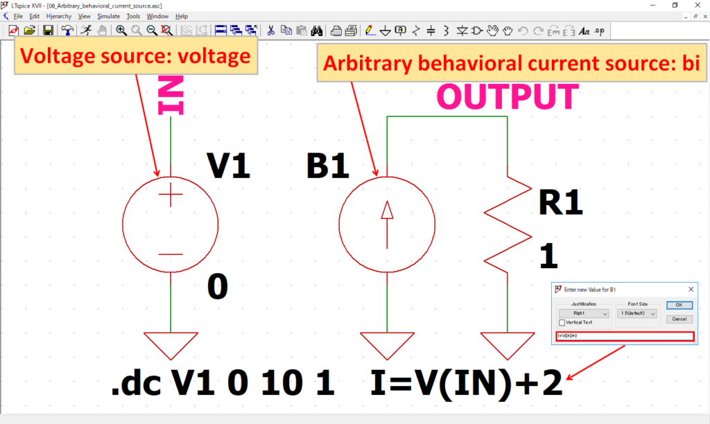
To check the operation of a arbitrary behavioral current source, we will create the above circuit.
To set the arbitrary behavioral current source, right-click on "I=F(…)" with the mouse and enter "I=V(IN)+2". Now the current obtained by adding 2A to V(IN) will be the output of the arbitrary behavioral current source.
The simulation will perform a DC sweep analysis and increase the voltage source V1 by 1V from 0 to 10V.

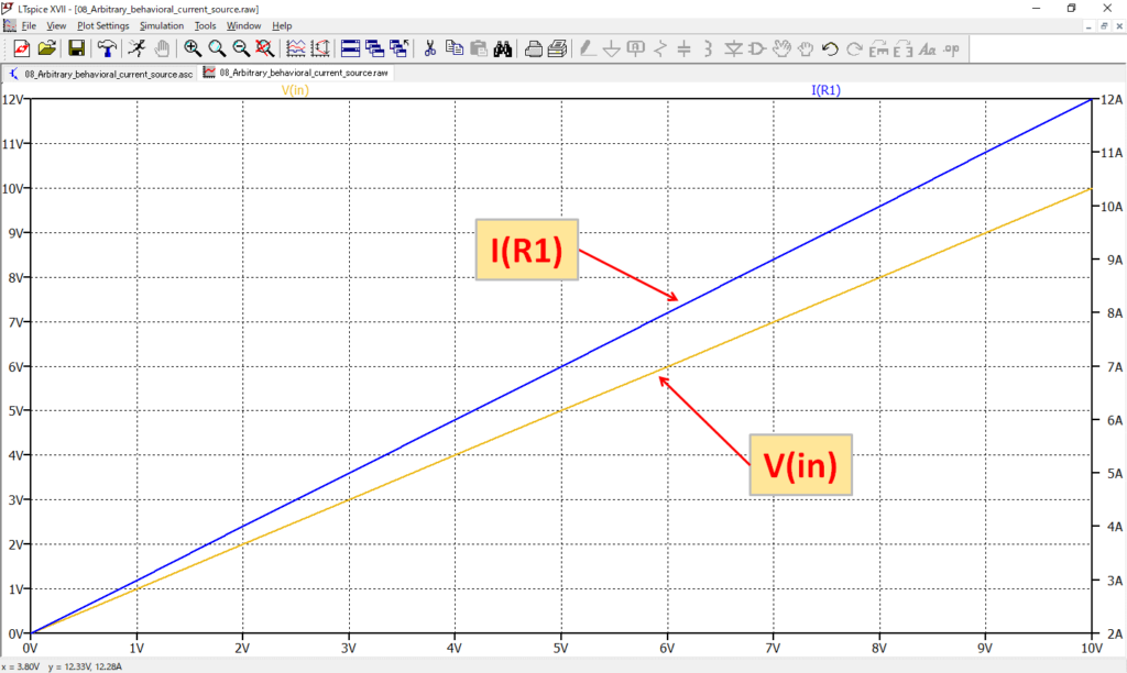
After the simulation, if you check the voltage and current waveforms of V(in) and I(R1), you can see that I(R1) is output at a voltage equal to V(in) plus 2A.
The schematic used in this simulation of a arbitrary behavioral current source can be downloaded from the link below.