Op-Amp Inverting Amplifier Circuit
In this article, "Op-Amp Inverting Amplifier Circuit" will be explained in detail.
The inverting amplifier circuit is the most basic of all op-amps and is often used in other application circuits.
Op-Amp Inverting Amplifier Characteristics
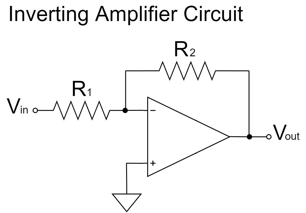
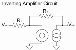
Inverting Amplifier Circuit
$$V_{out}=-\frac{R_2}{R_1}V_{in}$$
As shown in the equation above, the inverting amplifier circuit amplifies $V_{in}$ by a factor of $\frac{R_2}{R_1}$ and outputs it to $V_{out}$.
Also, the $V_{out}$ signal is inverted, as indicated by the "$-$" polarity.
For example, if $R_1=1kΩ, R_2=10kΩ, V_{in}=1V$;
$$V_{out}=-\frac{10k}{1k} \times 1=-10[V]$$
- Output signal is input signal inverted
- Wide range of amplification factor settings (buffer and attenuator also possible)
- Electrically stable in operation
- Input impedance is input resistance
- Output impedance is almost 0
Output signal is input signal inverted
In the op-amp inverting amplifier circuit, the phase of the input and output signals differ by 180° because the output signal is inverted of the input signal.
For example, if the input voltage is +, the output voltage will be -, and if the input voltage is -, the output voltage will be +.
If you do not want to invert the signal, connect two inverting amplifiers in series, which will result in "inverting + inverting => non-inverting".
Wide range of amplification factor settings (buffer and attenuator also possible)
The ratio of the op-amp inverting amplifier circuit is $\frac{R_2}{R_1}$, which gives a wide range of amplification ratio settings.
Therefore, various inverting amplification circuits can be made: amplifier if $R_2 \gt R_1$, buffer with 1x amplification factor if $R_2=R_1$, and attenuator if $R_2 \lt R_1$.
Electrically stable in operation
The op-amp inverting amplifier circuit is electrically stable in operation.
In an op-amp, the $+$ and $-$ pins are virtually shorted inside the op-amp.
In the case of the op-amp inverting amplifier circuit, since the $+$ pin is connected to GND, we can assume that the $-$ pin is also connected to GND through a virtual short circuit.
Therefore, the operating point is fixed at the GND potential (0 V), and the op-amp inverting amplifier circuit has the advantage of good circuit characteristics and can easily be used in other application circuits.
Input impedance is input resistance
For the op-amp inverting amplifier circuit, $R_1$ is the input impedance because the input impedance is the input resistance.
As explained in "Electrically stable in operation," we can assume that the $+$ and $-$ pins are virtually shorted inside the op amp.
In the case of the op-amp inverting amplifier circuit, since the $+$ pin is connected to GND, we can assume that the $-$ pin is also connected to GND through a virtual short circuit.
From the input of the op-amp inverting amplifier circuit, $R_1$ is connected to GND, so $R_1$ is the input impedance.
Therefore, if the input impedance of the op-amp inverting amplifier circuit is too low, a voltage drop will occur.
Output impedance is almost 0
The output impedance of the op-amp inverting amplifier circuit is kept at a voltage that satisfies the equation $V_{out}=-\frac{R_2}{R_1}V_{in}$ by the negative feedback, so it is almost zero.
Therefore, it is almost unaffected by the input impedance of the circuit connected to the output pin of the op-amp, and the required signal level can be extracted without causing a voltage drop.
Op-Amp Inverting Amplifier Equations(Formulas)
To obtain the equation for the op-amp inverting amplifier circuit, a calculation is made from the equation for the voltage of each part of the circuit and the ideal op-amp is replaced by the nullor model.
Equation Example 1
Op-Amp Schematic Symbol
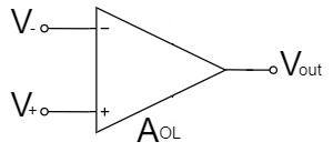
The op-amp amplifies the potential difference between the two input voltages, $V_+$ and $V_-$, with an open-loop gain $A_{OL}$.
$$V_{out}=A_{OL}(V_+-V_-)$$
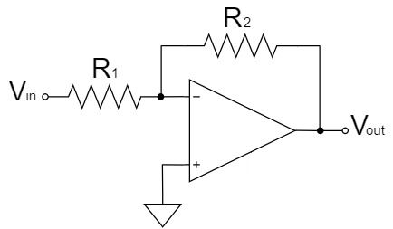
Inverting Amplifier Circuit
In the case of the op-amp inverting circuit, the $+$ pin is connected to GND, so the $V_+$ is:
$$V_+=0$$
As a result of the above, $V_{out}$ is:
$$V_{out}=A_{OL}(0-V_-)=-A_{OL}V_-\cdots(1)$$
Also, since the $-$ pin of the inverting amplifier circuit has high input impedance and no current can flow through it, the circuit can be represented as shown below:
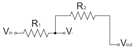
By the superposition theorem, $V_-$ can be easily obtained as a voltage divider circuit by dividing the above circuit into two parts.
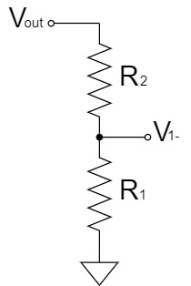
$$V_{1-}=\frac{R_1}{R_1+R_2}V_{out}$$
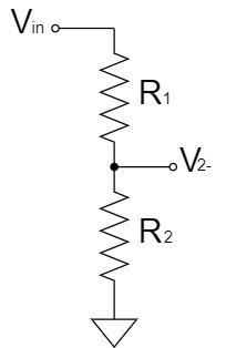
$$V_{2-}=\frac{R_2}{R_1+R_2}V_{in}$$
Thus, $V_-$ is:
$$V_{-}=V_{1-}+V_{2-}$$
$$V_-=\frac{R_1}{R_1+R_2}V_{out}+\frac{R_2}{R_1+R_2}V_{in}\cdots(2)$$
By substituting Eq.(2) into Eq.(1), $V_{out}$ is:
$$V_{out}=-A_{OL}\left(\frac{R_1}{R_1+R_2}V_{out}+\frac{R_2}{R_1+R_2}V_{in}\right)$$
$$V_{out}=-\frac{R_1}{R_1+R_2}A_{OL}V_{out}-\frac{R_2}{R_1+R_2}A_{OL}V_{in}$$
$$V_{out}+\frac{R_1}{R_1+R_2}A_{OL}V_{out}=-\frac{R_2}{R_1+R_2}A_{OL}V_{in}$$
$$\frac{R_1+R_2}{R_1+R_2}V_{out}+\frac{A_{OL}R_1}{R_1+R_2}V_{out}=-\frac{R_2}{R_1+R_2}A_{OL}V_{in}$$
$$\frac{R_1+R_2+A_{OL}R_1}{R_1+R_2}V_{out}=-\frac{R_2}{R_1+R_2}A_{OL}V_{in}$$
$$V_{out}=-\frac{R_2}{R_1+R_2+A_{OL}R_1}A_{OL}V_{in}$$
$$V_{out}=-\frac{A_{OL}R_2}{R_1+R_2+A_{OL}R_1}V_{in}$$
$$V_{out}=-\frac{R_2}{R_1}\frac{A_{OL}}{1+\frac{R_2}{R_1}+A_{OL}}V_{in}$$
$$V_{out}=-\frac{R_2}{R_1}\frac{1}{\frac{1}{A_{OL}}+\frac{1}{A_{OL}}\frac{R_2}{R_1}+1}V_{in}$$
$$V_{out}=-\frac{R_2}{R_1}\frac{1}{\frac{1}{A_{OL}}(1+\frac{R_2}{R_1})+1}V_{in}$$
Given that $A_{OL}$ is an extremely large value (∞), $\frac{1}{A_{OL}}⇒0$:
$$V_{out}=-\frac{R_2}{R_1}V_{in}$$
Equation Example 2
Inverting Amplifier Circuit
In the case of the op-amp inverting circuit, the $+$ pin is connected to GND, so the $V_+$ is:
$$V_+=0$$
Furthermore, the $+$ and $-$ pins can be considered to be connected through a virtual short.
$$V_-=V_+=0\cdots(1)$$
Also, since the $-$ pin of the inverting amplifier circuit has high input impedance and no current can flow through it, the circuit can be represented as shown below:
By the superposition theorem, $V_-$ can be easily obtained as a voltage divider circuit by dividing the above circuit into two parts.
$$V_{1-}=\frac{R_1}{R_1+R_2}V_{out}$$
$$V_{2-}=\frac{R_2}{R_1+R_2}V_{in}$$
Thus, $V_-$ is:
$$V_{-}=V_{1-}+V_{2-}$$
$$V_-=\frac{R_1}{R_1+R_2}V_{out}+\frac{R_2}{R_1+R_2}V_{in}\cdots(2)$$
By substituting Eq.(2) into Eq.(1), $V_{out}$ is:
$$0=\frac{R_1}{R_1+R_2}V_{out}+\frac{R_2}{R_1+R_2}V_{in}$$
$$\frac{R_1}{R_1+R_2}V_{out}=-\frac{R_2}{R_1+R_2}V_{in}$$
$$V_{out}=-\frac{R_2}{R_1}V_{in}$$
Equation Example 3(Using Nullor Model)
Inverting Amplifier Circuit
We replace the ideal op-amp with the nullor model and calculate the inverting amplifier circuit as shown below:
The Nullor model can represent a virtual short in an op amp, which simplifies the calculation.
For a more detailed explanation of the nullor model, please refer to the following article.
Inverting Amplifier Circuit(Nullor Model)
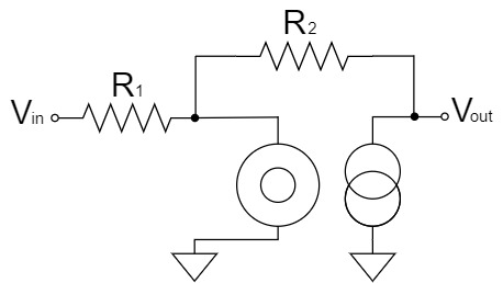
We will try to change the above schematic for clarity.
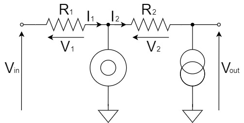
From Kirchhoff's Current Law(KCL), the relation between $I_1$ and $I_2$ is:
$$I_2=I_1$$
Also, $I_1$ and $I_2$ can be obtained respectively as shown below:
$$I_1=\frac{V_1}{R_1}=\frac{V_{in}}{R_1}\cdots(1)$$
$$I_2=\frac{V_2}{R_2}=\frac{-V_{out}}{R_2}=-\frac{V_{out}}{R_2}\cdots(2)$$
By substituting Eq.(1) and Eq.(2) into $I_2=I_1$, the equation for the inverting amplifier circuit is:
$$-\frac{V_{out}}{R_2}=\frac{V_{in}}{R_1}$$
$$V_{out}=-\frac{R_2}{R_1}V_{in}$$
Other Op-Amp Circuit Examples
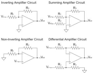
In this article, the "Op-Amp Inverting Amplifier Circuit" has been explained in detail, but there are various other circuits for op-amps as well.
Please refer to the following article for an introduction to the commonly used op-amp circuits.