Arduino-How to use Switch

This article details how to use switches with Arduino.
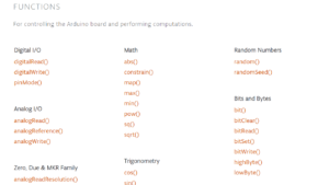
The input state of the switch is read by a program using Digital I/O functions.
For other Arduino functions and libraries, please refer to the following article.
What is Switch?
Switches are used in many ordinary households, and you probably use them on a regular basis to turn power on and off and select menus for lighting, TVs, air conditioners, and other electrical appliances.
- Toggle Switch
- Slide Switch
- DIP Switch
- Rotary Switch
- Tact Switch
- Pushbutton Switch
etc.
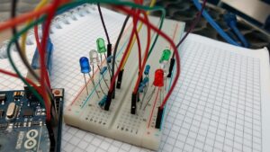
In this article, we will explain a sample program used with a switch, using a tact switch as an example, since it can be plugged directly into a breadboard.
Sample Programs (Sample Sketches)
In the sample program (sample sketch), a breadboard is used. For a detailed explanation of breadboards, please refer to the following article.
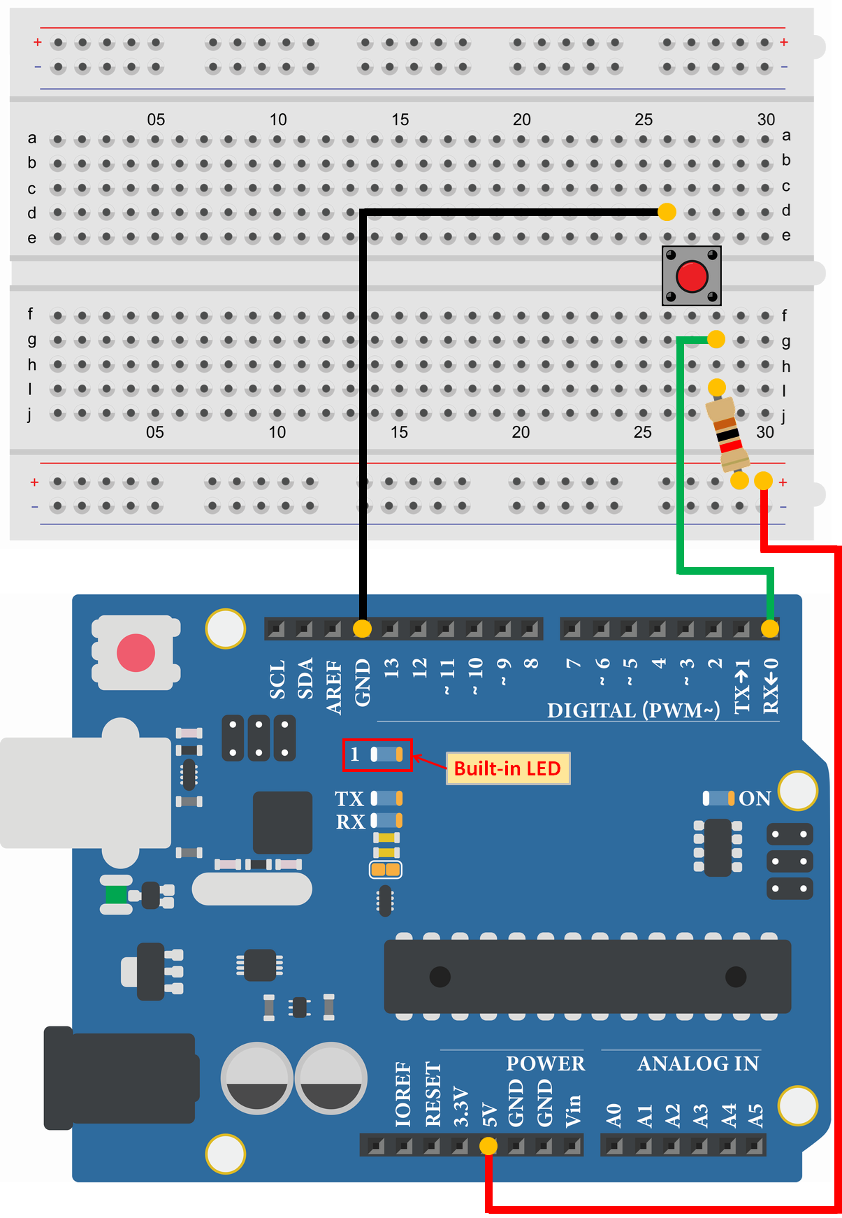
Reads the input status of the switch
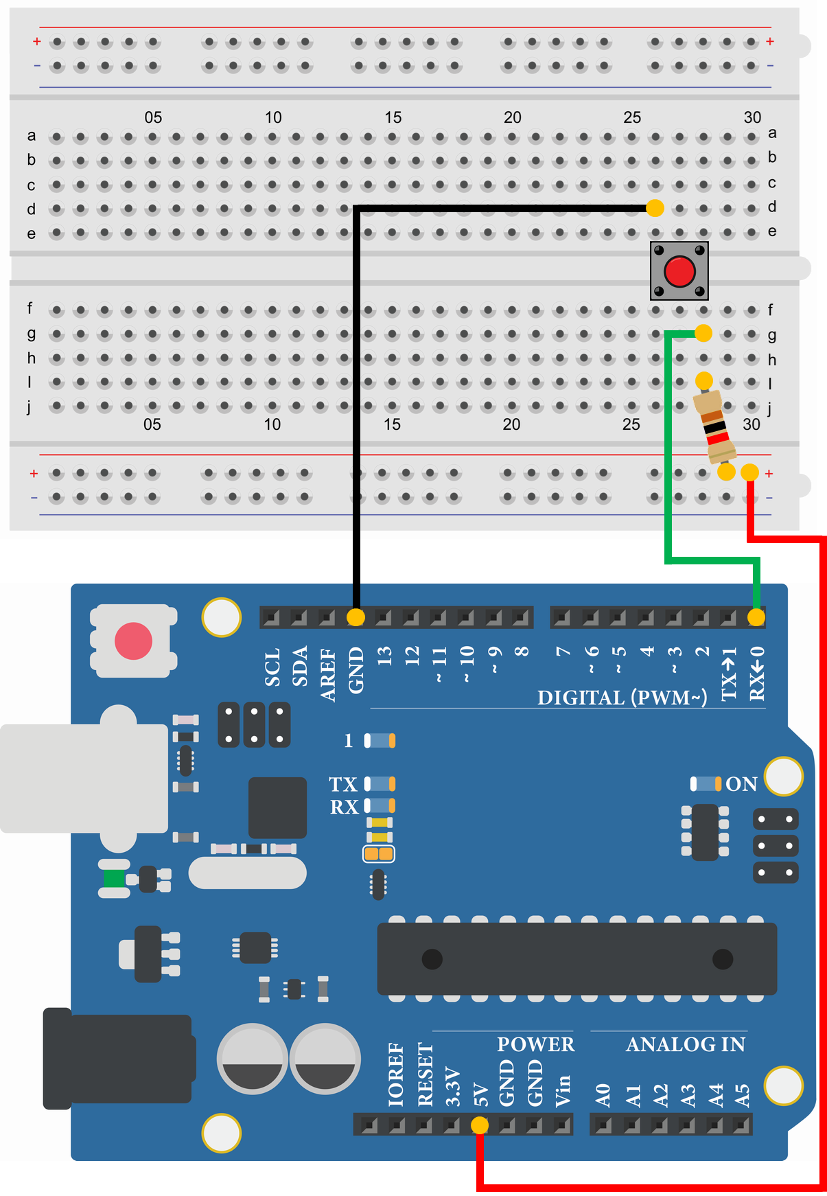
- Tact Switch
- Resistor 1kΩ
- Arduino Uno
- USB Cable
- Breadboard
- Jumper Wire
- PC(For Program Writing and Serial Monitor)
void setup() {
  pinMode(0, INPUT);//Set pin 0 as INPUT
  Serial.begin(9600);//Initialize serial communication at 9600bps
}

void loop() {
  boolean input;

  input = digitalRead(0);//Assign the input status of pin 0 (switch) to "input"
  Serial.println(input);//Send "input", New line
  delay(1000);//Wait 1000msec (1sec)
}1
1
1
0
0
0
1
1
1
1
The sample program displays the input status of the tact switch connected to pin 0 on a serial monitor.
The switch is pulled up, so '1' is displayed when the switch is OFF and '0' when the switch is ON.
Reads the input status of the switch(Input Pull-up)
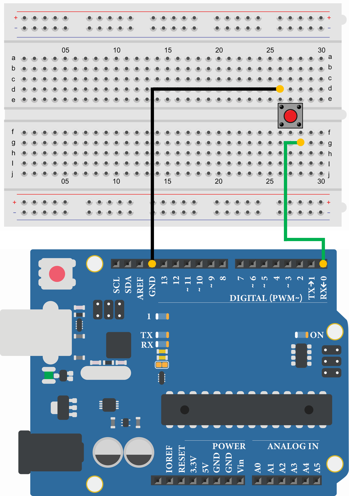
- Tact Switch
- Arduino Uno
- USB Cable
- Breadboard
- Jumper Wire
- PC(For Program Writing and Serial Monitor)
void setup() {
  pinMode(0, INPUT_PULLUP);//Set pin 0 as INPUT PULL-UP
  Serial.begin(9600);//Initialize serial communication at 9600bps
}

void loop() {
  boolean input;

  input = digitalRead(0);//Assign the input status of pin 0 (switch) to "input"
  Serial.println(input);//Send "input", New line
  delay(1000);//Wait 1000msec (1sec)
}1
1
1
0
0
0
1
1
1
1
The sample program displays the input status of the tact switch connected to pin 0 on a serial monitor.
By setting the digital I/O pins to "pinMode(0, INPUT_PULLUP)", the microcontroller's internal pull-up resistor can be used.
Therefore, it is not necessary to prepare and connect a pull-up resistor.
The switch is pulled up, so '1' is displayed when the switch is OFF and '0' when the switch is ON.
Switch on and LED lights up
- Tact Switch
- Resistor 1kΩ
- Arduino Uno
- USB Cable
- Breadboard
- Jumper Wire
- PC(For Program Writing and Serial Monitor)
void setup() {
  pinMode(0, INPUT);//Set pin 0 as INPUT
  pinMode(13, OUTPUT);//Set pin 13 as OUTPUT
}

void loop() {
  boolean input;

  input = digitalRead(0);//Assign the input status of pin 0 (switch) to "input"

  if(input == 0) {//Executed if the switch(pin 0) is ON
    digitalWrite(13, HIGH);//Pin 0 output set to HIGH (5V)
  }
  else {//Executed if the switch(pin 0) is OFF
    digitalWrite(13, LOW);//Pin 13 output set to LOW (0V)
  }
  delay(10);//Wait 10msec (0.01sec), Chattering prevention
}
In the sample program, the LED on the Arduino Uno board turns on and off based on the input state of the tact switch connected to pin 0. Pressing the tact switch turns on the LED and releasing it turns off the LED.
Count the number of times the switch is pressed
- Tact Switch
- Resistor 1kΩ
- Arduino Uno
- USB Cable
- Breadboard
- Jumper Wire
- PC(For Program Writing and Serial Monitor)
int count = 0;

void setup() {
  pinMode(0, INPUT);//Set pin 0 as INPUT
  Serial.begin(9600);//Initialize serial communication at 9600bps
}

void loop() {
  if(digitalRead(0) == 0) {//Executed if the switch(pin 0) is ON
    count = count + 1;//Add '1' to "count"
    Serial.print("COUNT:");//Send "COUNT:"
    Serial.println(count);//Send "count", New line
    while(digitalRead(0) == 0) {//Repeat if the switch(pin 0) is ON
      delay(10);//Wait 10msec (0.01sec), Chattering prevention
    }
  }
}COUNT:1
COUNT:2
COUNT:3
COUNT:4
COUNT:5
COUNT:6
COUNT:7
COUNT:8
COUNT:9
COUNT:10
The sample program displays the number of times the tact switch is pressed on the serial monitor.
To prevent switch chattering, "delay(10)" is added in the wile loop. Chattering causes the switch to turn on and off repeatedly when it is turned on, so delaying the time avoids chattering.
There are many other ways to program anti-chattering measures, and chattering may also be avoided by adding the anti-chattering circuit.