How to use a Breadboard
This article details the use of breadboards. Breadboards make it easy to experiment, prototype, and evaluate electronic circuits.
What is a Breadboard?
A breadboard is a board on which electronic components and jumper wires are inserted into holes on the board to create electronic circuits.
(The original word seems to come from "bread+board," a cutting board for bread.)
Breadboards allow electronic circuits to be assembled without soldering electronic components, making them ideal for experimentation, prototyping, and evaluation of electronic circuits.
However, electronic circuit design by professional engineers often uses surface-mount components rather than DIP components, so there are few opportunities to use breadboards for prototyping.
However, the use of breadboards is still alive and well in electronic circuit learning and education, as well as in electronic construction as a hobby.
Kits that include an Arduino board (microcontroller board), electronic components, and a breadboard are also available, and by purchasing these kits, you can quickly build an electronic circuit.
How to use a Breadboard
We will go on to explain how to use a "breadboard" using a breadboard with 30 horizontal rows as an example.
Wiring Rails and Power Rail(Parts Area and Power Supply Area)
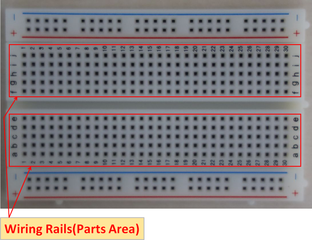
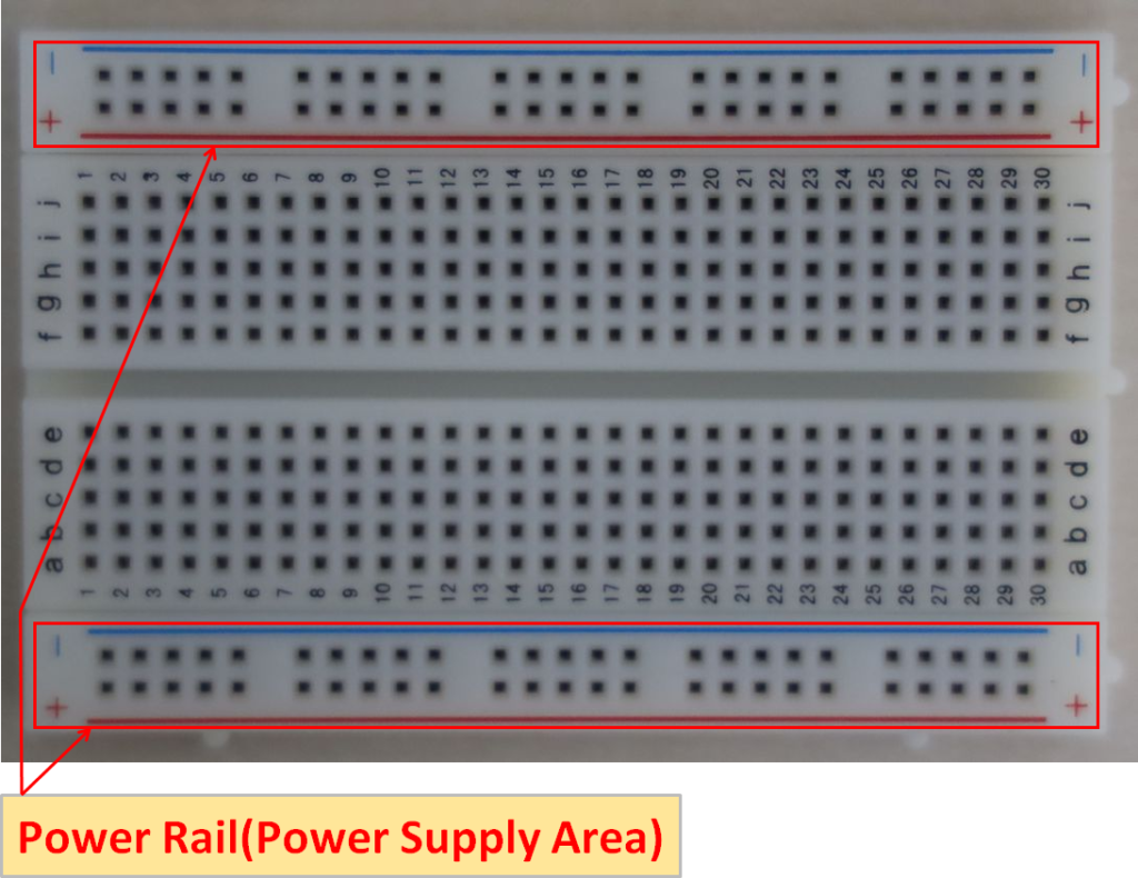
As shown above, breadboards are divided into two areas, one for wiring rails(parts area) and the other for power rail(power supply area), with mounting holes at a pitch of 2.54mm.
(Some breadboards do not have a power rail.)
Connections in the Breadboard
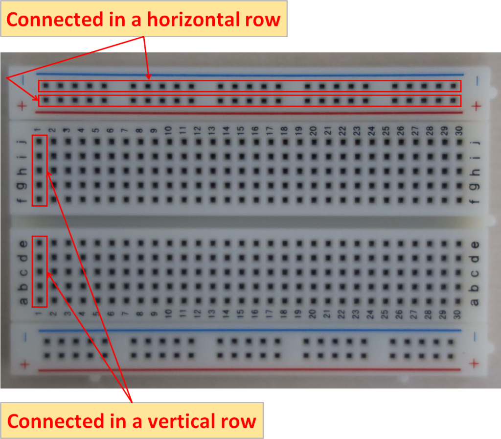
Breadboards have mounting holes connected in a regular pattern. Areas for components are connected vertically in a row and areas for power supply are connected horizontally in a row.
Jumper Wires for Breadboards
Jumper Wire Male-Male
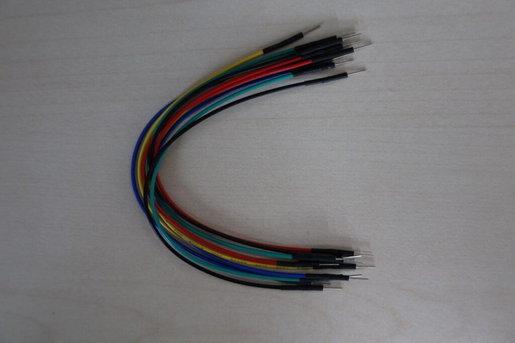
Rows that are not connected on the breadboard can be connected to each other using "jumper wires" that have both ends in the shape of a male. These flexible jumper wires are easier to use.
The socket on the Arduino board also has the same female shape as the breadboard, so the same male-to-male jumper wires can be used.
Jumper Wire(cut, stripped and pre-bent)
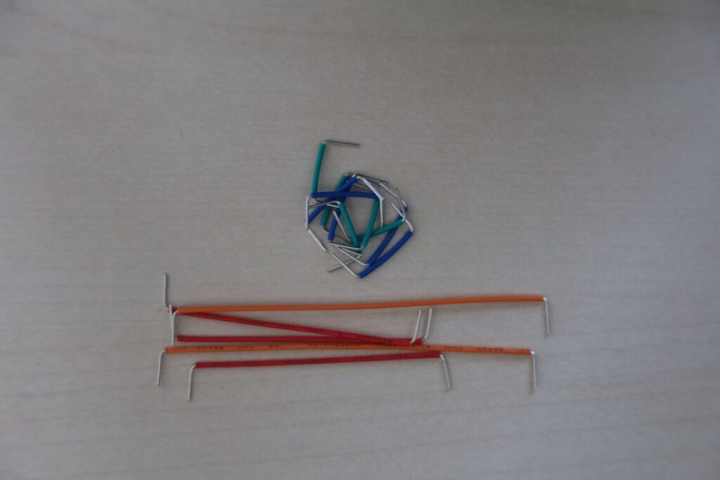
There are "jump wires" that have a fixed shape, but they lack flexibility and are difficult to use.
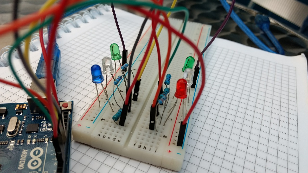
Breadboard Usage Example
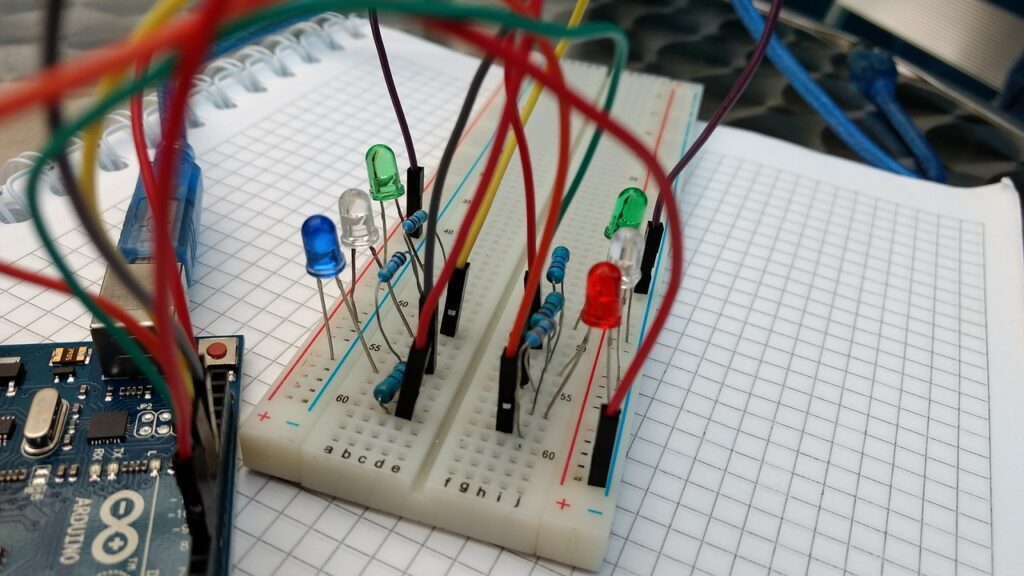
An image of an example breadboard use is shown above. By placing LEDs and current limiting resistors on the breadboard and connecting them to the Arduino board, a circuit is built to turn on the LEDs.