Arduino-How to use LED

This article details how to use LEDs (Light Emitting Diode) with Arduino.
Blinking LED is programmed in the Digital I/O functions.
For other Arduino functions and libraries, please refer to the following article.

What is LED (Light Emitting Diode)?
LEDs (Light Emitting Diodes) are electronic components that emit light when voltage is applied to the + side in the forward direction.
LEDs are relatively easy to handle among electronic components, so they are often the first thing you learn in electronics books.
Since LED is a power-saving light emitting element, many people use LED bulbs for home use. In addition, traffic signals, electric billboards, and street illumination are also being replaced by LED systems.
However, unlike light bulbs, LED will break if connected directly to a power source such as a battery, because too much current flows through it.
Therefore, it is usually necessary to connect a resistor in series to limit the current flowing through the LED.
For detailed LED current-limiting resistor calculations, please refer to the following article.
Sample Programs (Sample Sketches)
In the sample program (sample sketch), a breadboard is used. For a detailed explanation of breadboards, please refer to the following article.

Blinking Arduino Uno built-in LED
- Arduino Uno
- USB Cable
- PC(For Program Writing and Serial Monitor)
void setup() {
  pinMode(13, OUTPUT);//Set pin 13 as OUTPUT
}

void loop() {
  digitalWrite(13, HIGH);//Pin 13 output set to HIGH (5V)
  delay(1000);//Wait 1000msec (1sec)
  digitalWrite(13, LOW);//Pin 13 output set to LOW (0V)
  delay(1000);//Wait 1000msec (1sec)
}
The Arduino Uno has chip-type LEDs mounted on the board, so before blinking external LEDs, let's first blink the Arduino Uno's built-in LEDs as a practice.
In the sample program, the built-in LED is connected to pin 13 of the digital I/O, so pin 13 is set to output.
Then, in the program in loop(), set the output of pin 13 to HIGH (5V), wait for 1 second, set the output of pin 13 to LOW (0V), wait for 1 second, and repeat to make the Arduino Uno built-in LED blink at 1 second intervals.
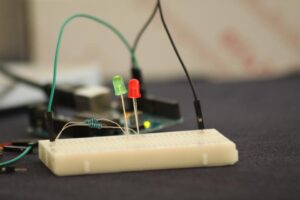
Blinking LED
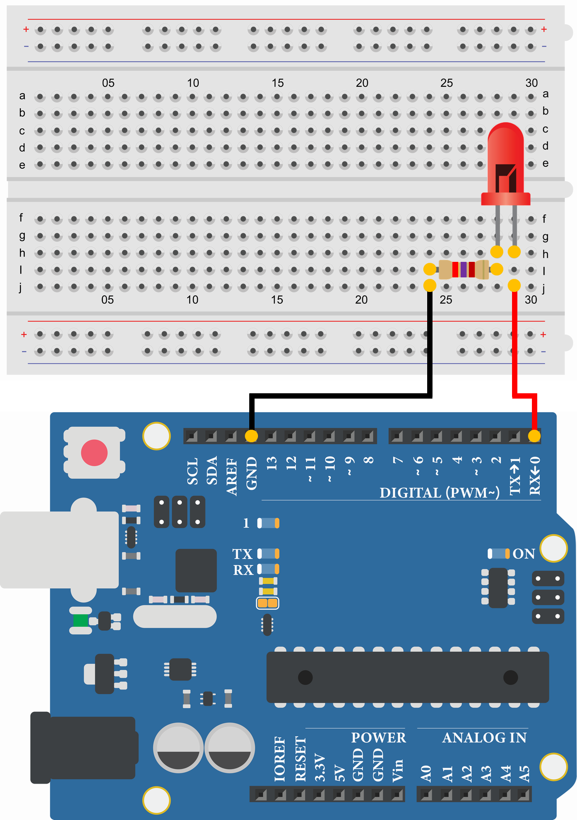
- LED Red
- Resistor 270Ω
- Arduino Uno
- USB Cable
- Breadboard
- Jumper Wire
- PC(For Program Writing and Serial Monitor)
void setup() {
  pinMode(0, OUTPUT);//Set pin 0 as OUTPUT
}

void loop() {
  digitalWrite(0, HIGH);//Pin 0 output set to HIGH (5V)
  delay(1000);//Wait 1000msec (1sec)
  digitalWrite(0, LOW);//Pin 0 output set to LOW (0V)
  delay(1000);//Wait 1000msec (1sec)
}
Since the sample program connects the external LED to pin 0, simply change the "Blinking Arduino Uno built-in LED" sample program from "pin 13" to "pin 0".
When the program is executed, the external LED blinks at 1-second intervals.