Arduino-How to use CdS Photoresistor
This article details how to use CdS photoresistors with Arduino.
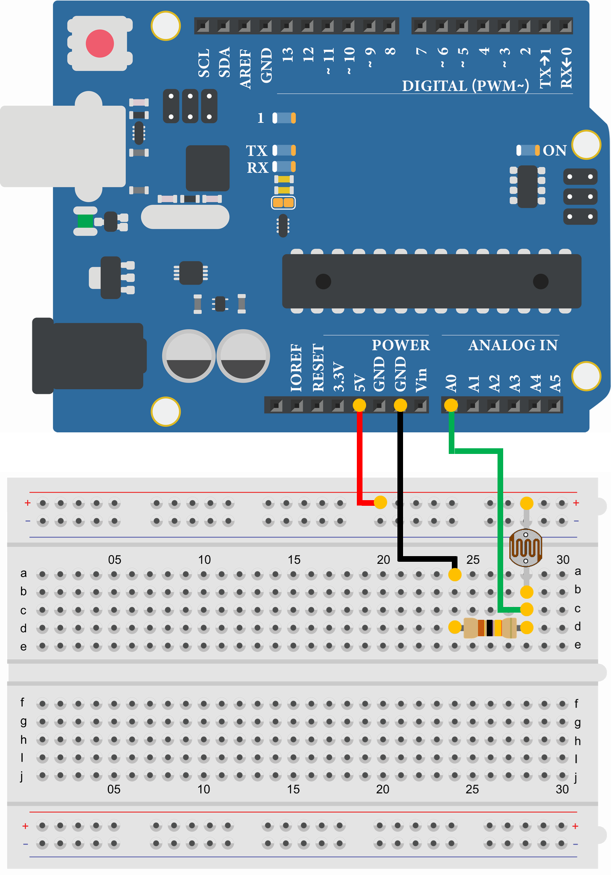
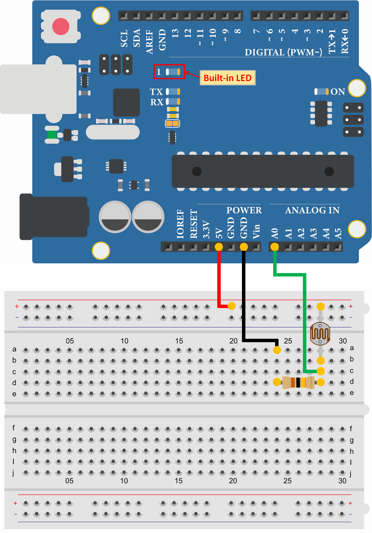
The voltage is read from a voltage divider circuit that combines a CdS photoresistor and a resistor with a program that uses Analog I/O functions.
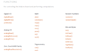
For other Arduino functions and libraries, please refer to the following article.
What is CdS Photoresistor?
A CdS photoresistor is an electronic component whose resistance changes depending on the brightness. Cadmium sulfide (CdS) is used as the internal material, and its resistance value decreases as the light hitting it becomes stronger.
For example, a 1MΩ CdS photoresistor (such as GL5528 or M1527) would be 1MΩ in dark conditions and 10-20KΩ in bright conditions (at 10 Lux).
Therefore, in the electronic circuit, a voltage divider circuit is created by combining a CdS photoresistor and a resistor to read a higher voltage value when it is bright and a lower voltage value when it is dark.
In this article, a voltage divider circuit combining a GL5528 (1MΩ CdS photoresistor) and a 10kΩ resistor will be used as an example.
Sample Programs (Sample Sketches)
In the sample program (sample sketch), a breadboard is used. For a detailed explanation of breadboards, please refer to the following article.
Read voltage from voltage divider circuit of CdS cell and resistor
- CdS Photoresistor GL5528
- Resistor 10kΩ
- Arduino Uno
- USB Cable
- Breadboard
- Jumper Wire
- PC(For Program Writing and Serial Monitor)
void setup() {
  Serial.begin(9600);//Initialize serial communication at 9600bps
}

void loop() {
  int analog_data;
  float voltage;

  analog_data = analogRead(0);//Assign the input status of analog pin 0 to "analog_data"

  voltage = float(analog_data) * (5.0/1023.0);//Calculate voltage from A/D values
  Serial.print(voltage);//Send "voltage"
  Serial.println("V");//Send "V", New line
  delay(1000);//Wait 1000msec (1sec)
}2.40V
2.39V
0.21V
0.21V
0.20V
2.22V
2.35V
The sample program reads the voltage from the voltage divider circuit of the CdS photoresistor and resistor and displays it on a serial monitor.
Since "analogRead()" uses a 10-bit A/D converter, it reads values from 0 to 1023 for a range of 0 to 5V. Therefore, the voltage is calculated by multiplying the value read by (5/1023) in the program.
With this voltage divider circuit, the brightness of about room level (10Lux) is about 1.6 to 2.5V, and when it gets dark, the voltage is almost 0V.
LED lights up when dark
- CdS Photoresistor GL5528
- Resistor 10kΩ
- Arduino Uno
- USB Cable
- Breadboard
- Jumper Wire
- PC(For Program Writing and Serial Monitor)
void setup() {
  pinMode(13, OUTPUT);//Set pin 13 as OUTPUT
  Serial.begin(9600);//Initialize serial communication at 9600bps
}

void loop() {
  int analog_data;
  float voltage;

  analog_data = analogRead(0);//Assign the input status of analog pin 0 to "analog_data"
  voltage = float(analog_data) * (5.0/1023.0);//Calculate voltage from A/D values

  if(voltage < 1.0) {//Executed if the voltage of analog pin 0 is less than 1V
    digitalWrite(13, HIGH);//Pin 0 output set to HIGH (5V)
  }
  else {//Executed if the voltage of analog pin 0 is not less than 1V
    digitalWrite(13, LOW);//Pin 13 output set to LOW (0V)
  }
  delay(1000);//Wait 1000msec (1sec)
}
The sample program reads the voltage from the voltage divider circuit of the CdS cell and resistor, and the built-in LED on the Arduino Uno lights up when it is dark.
If the voltage of the voltage divider circuit is less than 1V, the LED is determined to be dark and the LED is turned on; otherwise, the LED is turned off.