LTspice-Independent Voltage Source Setting
LTspice requires setting of the signal source when simulating.
In this article, we will focus on how to set up a independent voltage source for analysis.
For the types of analysis, please see the following article.

How to open "Independent Voltage Source"
Signal source settings can be made on the "Independent Voltage Source" screen.
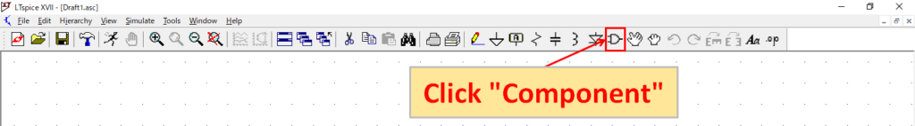
Click "Component" from the toolbar of the schematic editor screen.
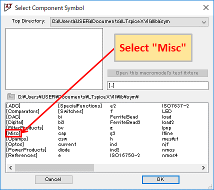
Select "Misc" and click "OK" or double-click "Misc".
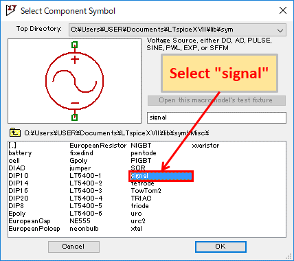
Select "signal" and click "OK" or double-click "signal".
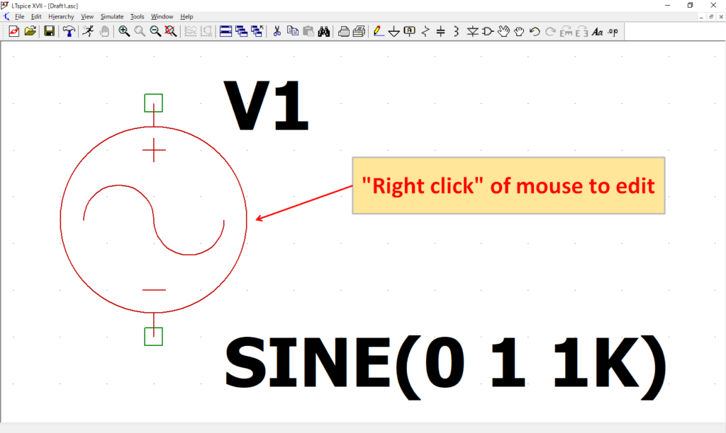
After placing "signal" on the schematic, "right click" of the mouse to open the editing screen.
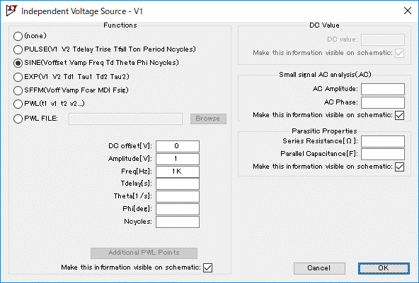
The “Independent Voltage Source” screen opens and you can set the signal source.
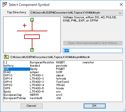
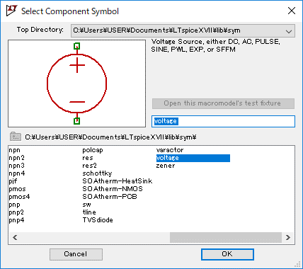
Component models of "cell" and "voltage" can also be used as signal sources. However, I think that it is better to use the part model of "signal" as a signal source as it is indistinguishable from the usual power supply.
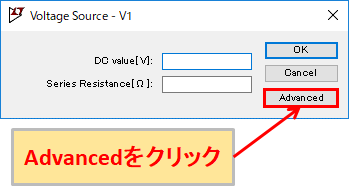
If you want to set the signal source in "cell" and "voltage", right click of the mouse on the part of the schematic, and the screen of the above image will appear. Click "Advanced".
Then, the “Independent Voltage Source” screen opens, and you can set the signal source.
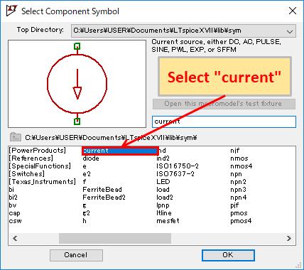
Although this article describes how to set up a "Independent voltage source", you can set up a "Independent current source" as well.
Common settings
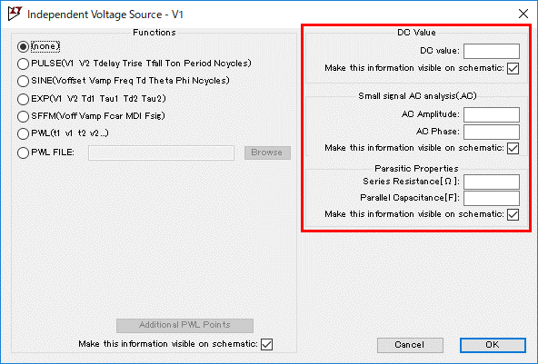
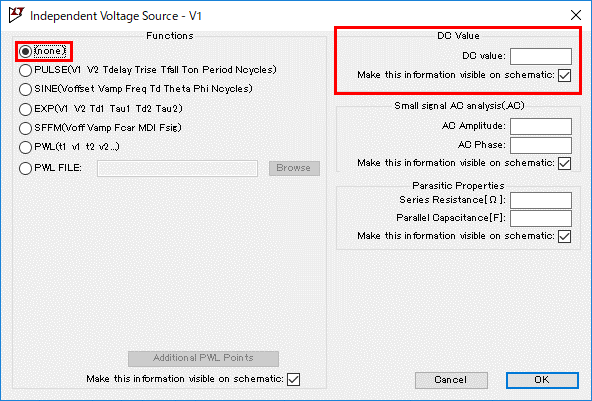
In "Independent Voltage Source", "DC Value", "Small signal AC analysis (. AC)" and "Parasitic Properties" can be set in "Common Settings".
DC Value
| Setting | Explanation |
|---|---|
| DC value | DC voltage value |
※This can be set only when "none" is selected in "Function".
Small signal AC analysis(.AC)
| Setting | Explanation |
|---|---|
| AC Amplitude | Amplitude of AD waveform |
| AC Phase | Phase of AC waveform |
※Set when simulating AC analysis (.ac).
Parasitic Properties
| Setting | Explanation |
|---|---|
| Series Resistance[Ω] | Series resistance value |
| Parallel Capacitance[F] | Parallel capacity value |
Functions
none(DC signal)
| Setting | Explanation |
|---|---|
| DC value | DC voltage value |
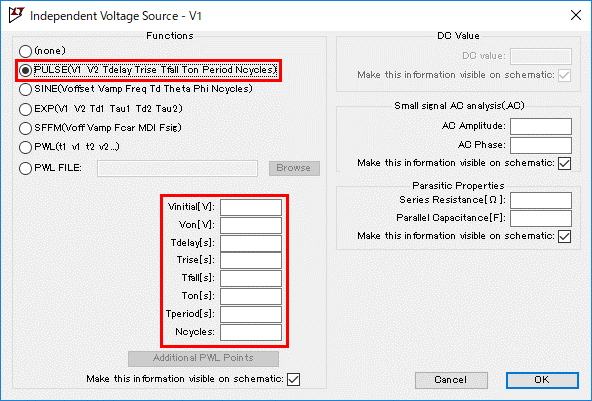
PULSE
| Setting | Explanation |
|---|---|
| Vinitial[V] | LOW level voltage value |
| Von[V] | HIGH level voltage value |
| Tdelay[s] | Delay time from 0 to operation start |
| Trise[s] | Rise time from LOW to HIGH |
| Tfall[s] | Fall time from HIGH to LOW |
| Ton[s] | HIGH level time |
| Tperiod[s] | One cycle time |
| Ncycles | Repeat count (Continuous output if not input) |
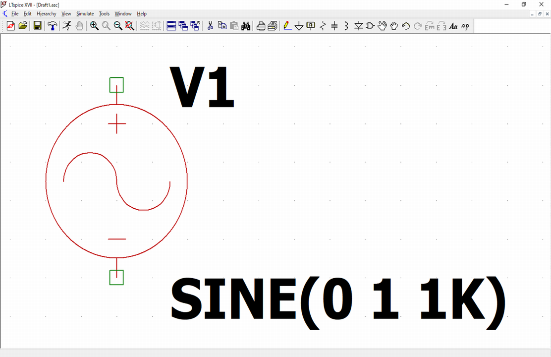
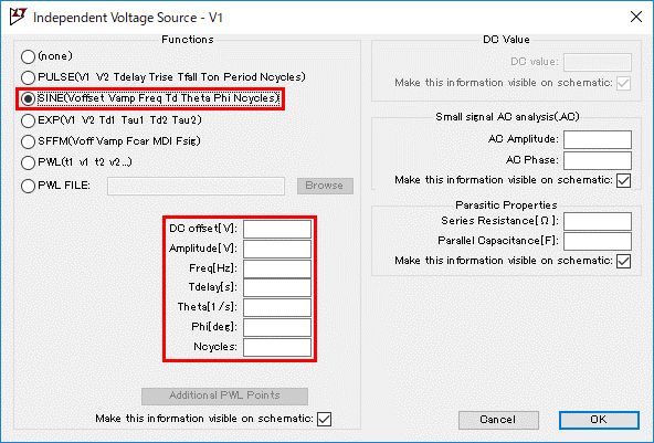
SINE
| Setting | Explanation |
|---|---|
| DC offset[V] | Offset voltage value |
| Amplitude[V] | Amplitude voltage value |
| Freq[Hz] | Oscillation frequency |
| Tdelay[s] | Delay time from 0 to operation start |
| Theta[1/s] | Damping coefficient |
| Phi[deg] | Phase difference |
| Ncycles | Repeat count (Continuous output if not input) |
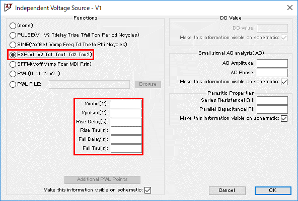
EXP(Exponential pulse wave)
| Setting | Explanation |
|---|---|
| Vinitial[V] | LOW level voltage value |
| Vpulsed[V] | Maximum value of HIGH level |
| Rise Delay[V] | Delay time until waveform rises |
| Rise Tau[s] | Rise time constant of waveform |
| Fall Delay[s] | Delay time until the waveform falls |
| Fall Tau[s] | Fall time constant of waveform |
SFFM(FM wave)
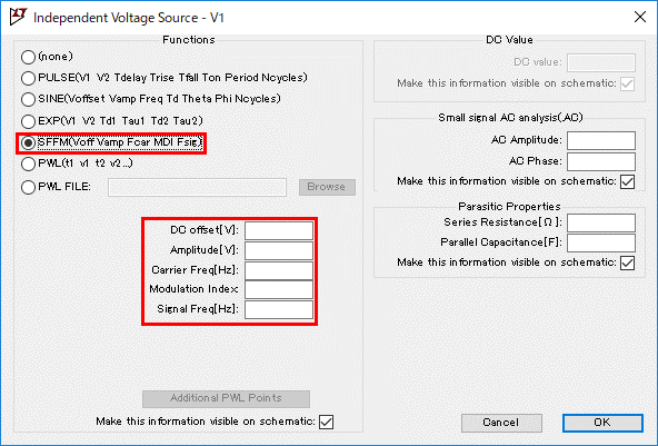
| Setting | Explanation |
|---|---|
| DC offset[V] | Carrier offset voltage value |
| Amplitude[V] | Amplitude of SINE carrier waveform |
| Carrier Freq[Hz] | Carrier frequency |
| Modulation Index | Modulation Index |
| Signal Freq[Hz] | Signal frequency |
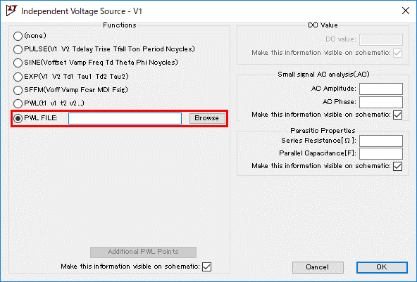
PWL(Piece Wise Liner wave)
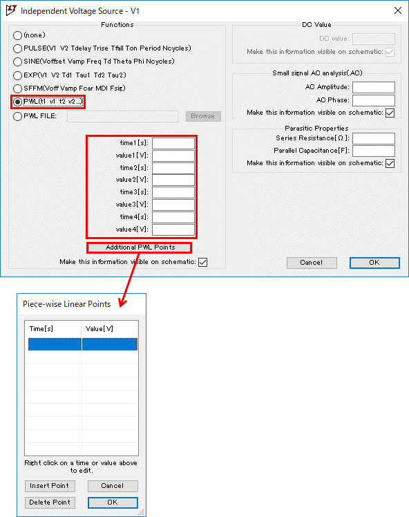
| Setting | Explanation |
|---|---|
| time[s] | n time |
| value[V] | Voltage value at n time |
PWL FILE(PWL wave file input)