LTspice-Switch Types
This article introduces the various switche types in LTspice.
- Voltage controlled switch: sw
- Current controlled switch: csw
Voltage Controlled Switch
The voltage controlled switche can be switched ON/OFF by inputting an external voltage and changing the resistance value inside the switch.
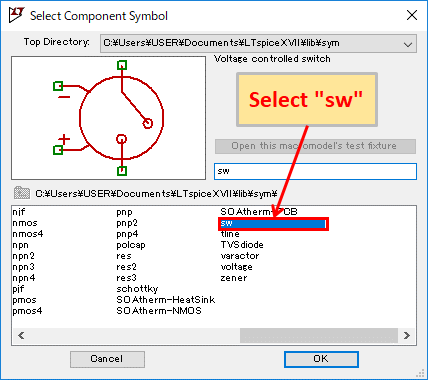
To use the voltage controlled switch, click on "Component" in the toolbar and select "sw" when creating the schematic.

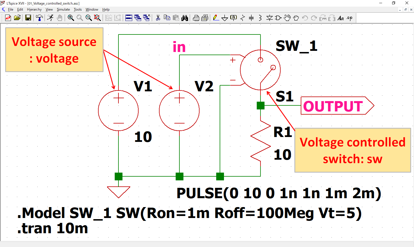
To check the operation of a voltage controlled switch, we will create the above circuit.
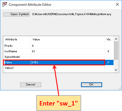
To set the voltage controlled switch, right-click with the mouse on the schematic symbol and enter the model name in the "Value". In this case, "SW_1" was entered.
It also describes the on-resistance value, off-resistance value, and voltage threshold of the voltage controlled switche in SPICE Directive.
When the voltage input to the voltage controlled switch is below the voltage threshold (LOW LEVEL), the switch becomes off-resistance value, and when the voltage is above the voltage threshold (HIGH LEVEL), the switch becomes on-resistance value.
By changing the resistance value from this external voltage, the voltage controlled switch can be switched ON/OFF.
This time, the model name: SW_1, on-resistance value: 1mΩ, off-resistance value: 100MΩ, and voltage threshold: 5V are described as follows.
.Model SW_1 SW(Ron=1m Roff=100Meg Vt=5)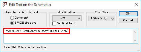
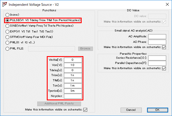
The signal source setting of V2 is set to generate pulses with LOW level: 0V, HIGH level: 10V, and frequency: 500 Hz.
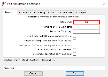
Also, the analysis setting sets the transient analysis time at 10msec.
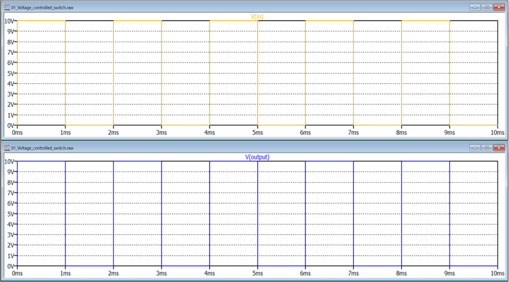
After the simulation, if you check the voltage waveforms of V(in) and V(output), you will see that the voltage (LOW/HIGH LEVEL) of V(in) and V(output) is changing at the same timing.
Therefore, when V(in) is 0V, the resistance value of the voltage controlled switch is 100MΩ and V(output) is 0V because it is below the threshold value of 5V.
And when V(in) is 10V, the resistance value of the voltage controlled switch is 1mΩ and V(output) is 10V because it is above the threshold value of 5V.
The schematic used in this simulation of a voltage controlled switch can be downloaded from the link below.
Current Controlled Switch
The current controlled switch can be switched ON/OFF by sensing an external current and changing the resistance value inside the switch.
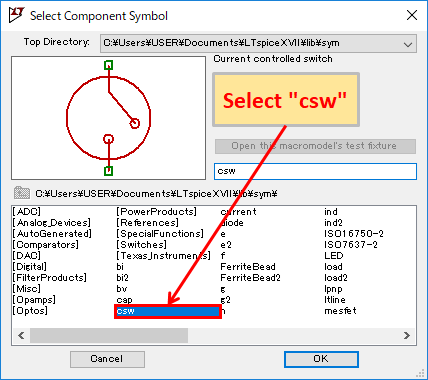
To use the current controlled switch, click on "Component" in the toolbar and select "csw" when creating the schematic.
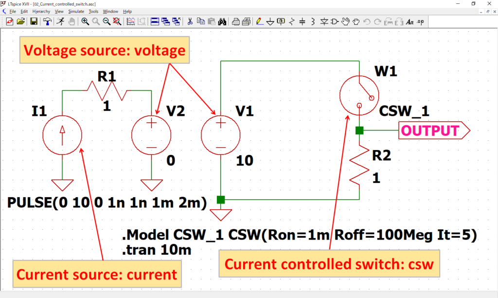
To check the operation of a current controlled switch, we will create the above circuit.
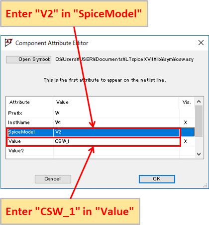
To set the current controlled switch, right-click with the mouse on the schematic symbol and enter the ammeter (voltage source) to detect the current in "SpiceModel" and the model name in "Value". In this case, "SpiceModel: V2" and "Value: CSW_1" were entered.
It also describes the on-resistance value, off-resistance value, and current threshold of the current controlled switche in SPICE Directive.
When the detected current is below the current threshold (LOW LEVEL), the switch becomes off-resistance value, and when the current is above the current threshold (HIGH LEVEL), the switch becomes on-resistance value.
By changing the resistance value from this detected current, the current controlled switch can be switched ON/OFF.
This time, the model name: SW_1, on-resistance value: 1mΩ, off-resistance value: 100MΩ, and current threshold: 5A are described as follows.
.Model SW_1 SW(Ron=1m Roff=100Meg It=5)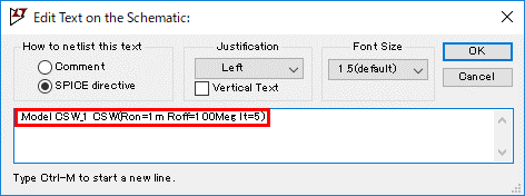
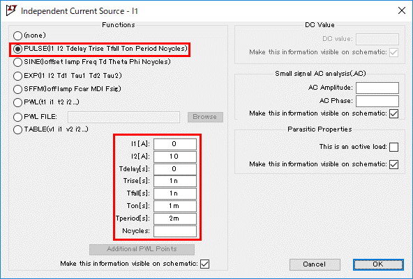
The signal source setting of I1 is set to generate pulses with LOW level: 0A, HIGH level: 10A, and frequency: 500 Hz.

Also, the analysis setting sets the transient analysis time at 10msec.
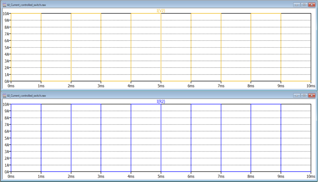
After the simulation, if you check the current waveforms of I(V2) and I(R2), you will see that the current (LOW/HIGH LEVEL) of I(V2) and I(R2) is changing at the same timing.
Therefore, when I(V2) is 0A, the resistance value of the current controlled switch is 100MΩ and I(R2) is 0A because it is below the threshold value of 5A.
And when I(V2) is 10V, the resistance value of the current controlled switch is 1mΩ and I(R2) is 10A because it is above the threshold value of 5A.
The schematic used in this simulation of a current controlled switch can be downloaded from the link below.