LTspice-Initial Setting
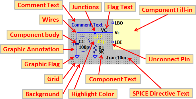
In this article, we will introduce the "Initial Settings" when installing the latest version of LTspice XVII.
Since LTspice allows you to make various settings in detail, there may be some confusion as to what to set.
But if you set the initial settings to be introduced from now on, it is almost all You should not be troubled.
Control Panel
With LTspice XVII, you can make various settings from the "Control Panel".
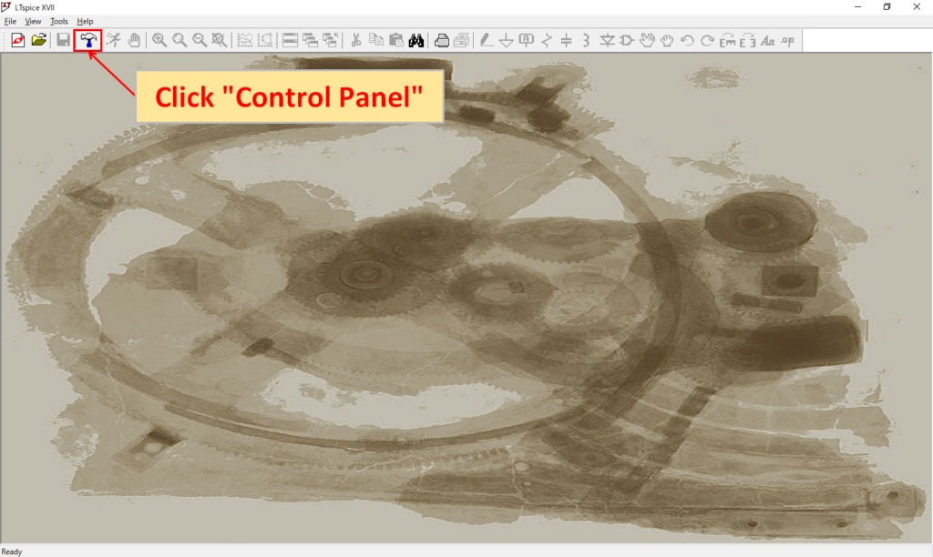
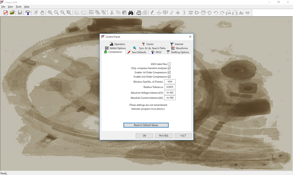
Launch LTspice XVII and click "Control Panel" (hammer icon) on the toolbar to display the "Control Panel" screen.
(It can also be displayed by clicking "Tools" -> "Control Panel" in the menu bar.)
If you make a mistake, you can return to the default state by clicking "Reset to Default Values".
In this article, we will introduce the minimum required setting method.
Setting of simulation speed and internal accuracy
If there is enough processing power of the PC, we recommend “Alternate”, which has high internal accuracy.
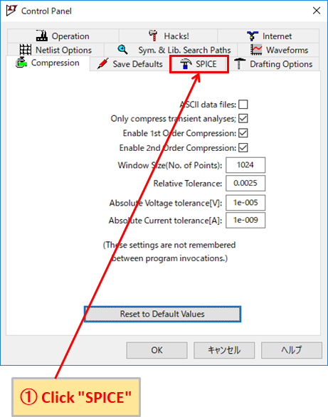
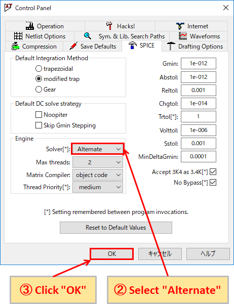
- Click "SPICE" in the "Control Panel".
- Select "Alternate" in "Engine" -> "Solver [*]".
- Click “OK” to finish setting.
- Normal:Simulation speed 2x, internal accuracy 1/1000 (Compared to Alternate)
- Alternate:Simulation speed 1/2, internal precision 1000 times (Compared to Normal)
Grid display in schematic editor
When creating a schematic, it is easier to see if the grid is displayed.
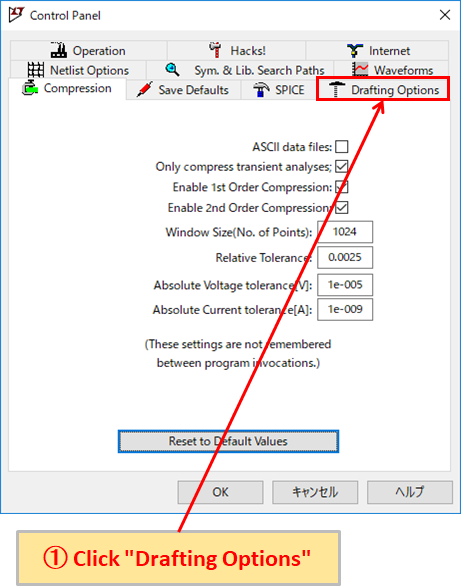
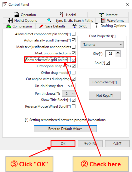
- Click "Drafting Options" in the Control Panel.
- Checking "Show schematic grid points [*]" will display the grid on the schematic editor.
- Click “OK” to finish setting.
Change keyboard shortcut
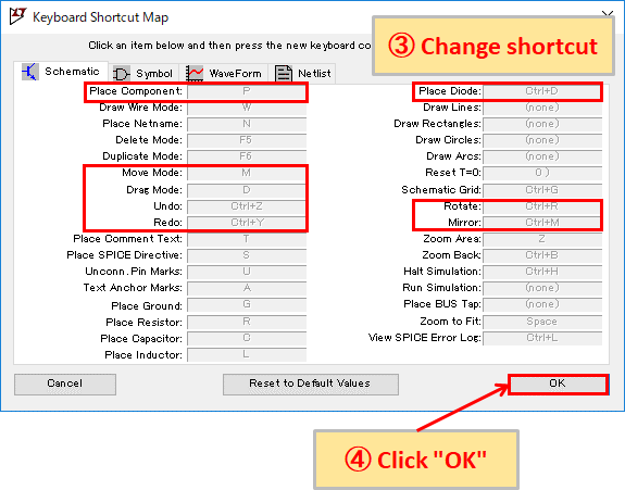
If you get used to circuit creation, it is much faster to use shortcuts. Some of the default shortcuts are F keys (function keys), so change them to characters that are easy to remember.

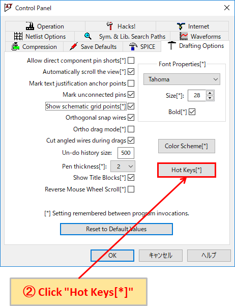
- Click "Drafting Options" in the Control Panel.
- If you click "Hot keys [*]", "Keyboard Shortcut Map" will be displayed.
- Change the keyboard shortcuts referring to the following table of "Recommended keyboard shortcuts".
- Click “OK” to finish setting.
Recommended keyboard shortcuts
| Command | Explanation | Before change | After change |
|---|---|---|---|
| Place Component | Select parts from the "Select Component Symbol" | F2 | P |
| Draw Wire Mode | Draw Wire | F3 | W |
| Place Net name | Place Net name | F4 | N |
| Move Mode | Move parts, wiring and etc. (It can move it by box.) | F7 | M |
| Drag Mode | Move it including wiring connected to parts (It can move it by box.) | F8 | D |
| Undo | Cancel operation | F9 | Ctrl+Z |
| Redo | Redo operation | Shift+F9 | Ctrl+Y |
| Place Diode | Place Diode | D | Ctrl+D |
| Mirror | Mirror parts | Ctrl+E | Ctrl+M |
| Zoom Area | Zoom in | Ctrl+Z | Z |
Automatically delete waveform data file
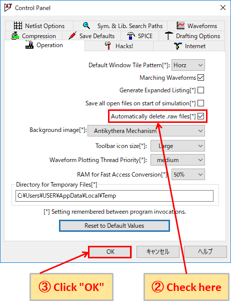
Because waveform data file is saved and it squeezes HDD (hard disk drive), let's try to delete waveform data automatically.
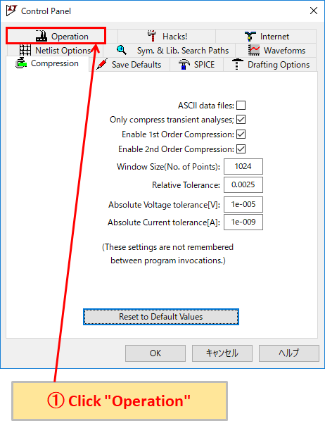
- Click "Operation" in the Control Panel.
- Checking "Automatically delate .raw files [*]" will automatically delete waveform data.
- Click “OK” to finish setting.
Display the schematic editor and waveform graph side by side
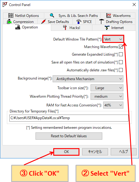
Depending on the configuration of the schematic and the contents of the simulation, it may be better to display the schematic editor and the waveform graph side by side. Please set as needed.

- Click "Operation" in the Control Panel.
- Select "Vert" in "Default Window Tile Pattern [*]".
- Click “OK” to finish setting.
Color Preferences
With LTspice XVII, you can change the color of WaveForm, schematic and netlist from Color Preferences.
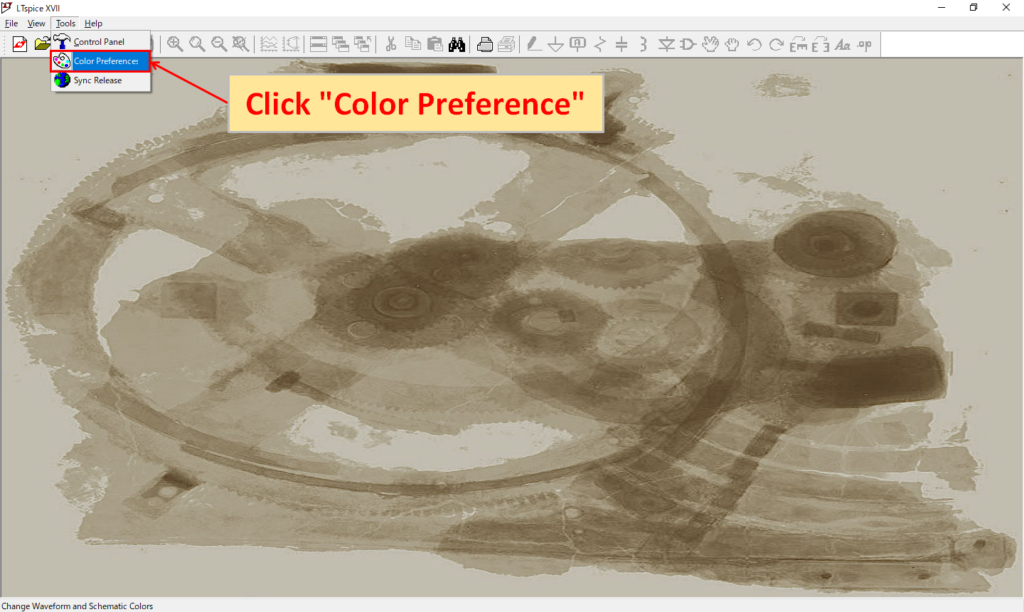
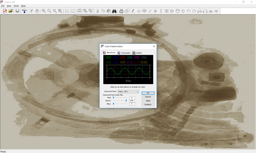
Launch LTspice XVII and click "Tools" -> "Color Preferences" in the menu bar to bring up the Color Palette Editor.
You can select the WaveForm, Schematic, or Netlist displayed on the tab, enter the RGB values, or move the slide bar to change each color. The RGB values of each color scheme are as follows for reference.
RGB of each color
| Color | R | G | B |
|---|---|---|---|
| White | 255 | 255 | 255 |
| Yellow | 255 | 255 | 0 |
| Orange | 255 | 165 | 0 |
| Gray | 128 | 128 | 128 |
| Light gray | 211 | 211 | 211 |
| Light blue | 173 | 216 | 230 |
| Green yellow | 173 | 255 | 47 |
| Ocher | 195 | 147 | 67 |
| Pink | 255 | 192 | 203 |
| Deep pink | 255 | 20 | 147 |
| Blue green | 0 | 164 | 151 |
| Red | 255 | 0 | 0 |
| Green | 0 | 128 | 0 |
| Purple | 128 | 0 | 128 |
| Brown | 165 | 42 | 42 |
| Blue | 0 | 0 | 255 |
| Navy | 0 | 0 | 128 |
| Black | 0 | 0 | 0 |
There is no problem in setting it to your own preference basically, but this article will introduce you to the recommended color.
Also, if you make a mistake, click "Defaults" and you'll be back to the default setting.
WaveForm
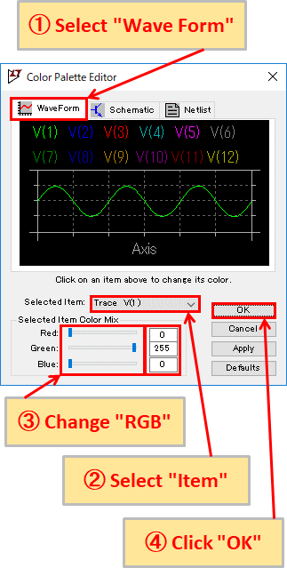
- Click "WaveForm" in the Color Palette Editor.
- Select "Item for which you want to change the color" under Selected item.
- Change the RGB values with numbers or change them with the slide bar to make it your favorite color.
- Click “OK” to finish setting.
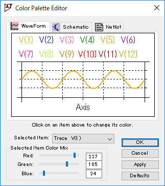
The color scheme is easy to understand if it is the same as the color of the oscilloscope waveform.
This article introduces recommended waveform color of high-share Tektronix and Keysight oscilloscopes as a reference.
Recommended color of WaveForm for Tektronix oscilloscope users
| Setting | Color | Red | Green | Blue |
|---|---|---|---|---|
| Trace V(1) | Moon yellow | 237 | 185 | 24 |
| Trace V(2) | Blue | 0 | 0 | 255 |
| Trace V(3) | Hot pink | 255 | 105 | 180 |
| Trace V(4) | Green | 0 | 128 | 0 |
| Trace V(5) | Orange | 255 | 165 | 0 |
| Trace V(6) | Purple | 128 | 0 | 128 |
| Trace V(7) | Deep pink | 255 | 20 | 147 |
| Trace V(8) | Green yellow | 173 | 255 | 47 |
| Trace V(9) | Dark goldenrod | 175 | 128 | 0 |
| Trace V(10) | Red | 255 | 0 | 0 |
| Trace V(11) | Maroon | 128 | 0 | 0 |
| Trace V(12) | Citrus | 175 | 175 | 0 |
| Axis | Black | 0 | 0 | 0 |
| Inactive Axis | Black | 0 | 0 | 0 |
| Grid | Black | 0 | 0 | 0 |
| Background | White | 255 | 255 | 255 |
Recommended color of WaveForm for Keysight oscilloscope users
| Setting | Color | Red | Green | Blue |
|---|---|---|---|---|
| Trace V(1) | Moon yellow | 237 | 185 | 24 |
| Trace V(2) | Green | 0 | 128 | 0 |
| Trace V(3) | Blue | 0 | 0 | 255 |
| Trace V(4) | Red | 255 | 0 | 0 |
| Trace V(5) | Magenta | 255 | 0 | 255 |
| Trace V(6) | Gray | 128 | 128 | 128 |
| Trace V(7) | Orange | 255 | 165 | 0 |
| Trace V(8) | Green yellow | 173 | 255 | 47 |
| Trace V(9) | Dark goldenrod | 175 | 128 | 0 |
| Trace V(10) | Purple | 128 | 0 | 128 |
| Trace V(11) | Maroon | 128 | 0 | 0 |
| Trace V(12) | Citrus | 175 | 175 | 0 |
| Axis | Black | 0 | 0 | 0 |
| Inactive Axis | Black | 0 | 0 | 0 |
| Grid | Black | 0 | 0 | 0 |
| Background | White | 255 | 255 | 255 |
Schematic
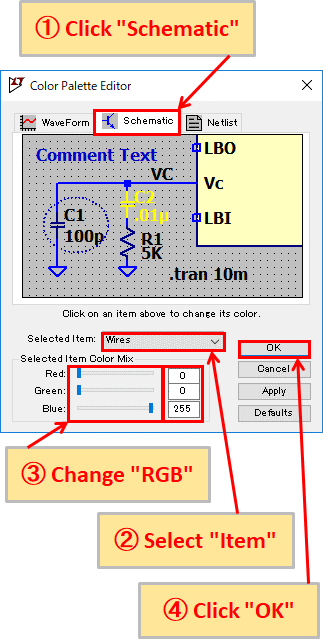
- Click "Schematic" in the Color Palette Editor.
- Select "Item for which you want to change the color" under Selected item.
- Change the RGB values with numbers or change them with the slide bar to make it your favorite color.
- Click “OK” to finish setting.
The circuit diagram is almost my preference, but it is set as follows.
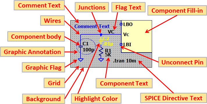
Schematic recommended color
| Setting | Color | Red | Green | Blue |
|---|---|---|---|---|
| Wires | Green | 0 | 128 | 0 |
| Junctions | Green | 0 | 128 | 0 |
| Component body | Free speech red | 192 | 0 | 0 |
| Graphic Flag | Free speech red | 192 | 0 | 0 |
| Component Fill-in | Cumulus | 255 | 255 | 192 |
| Component Text | Black | 0 | 0 | 0 |
| Flag Text | Deep pink | 255 | 20 | 147 |
| SPICE Directive Text | Black | 0 | 0 | 0 |
| Comment Text | Medium blue | 0 | 0 | 200 |
| Unconnect Pin | Green | 0 | 128 | 0 |
| Highlight Color | Orange | 255 | 165 | 0 |
| Grid | Black | 0 | 0 | 0 |
| Graphic Annotation | Blue green | 0 | 164 | 151 |
| Background | White | 255 | 255 | 255 |
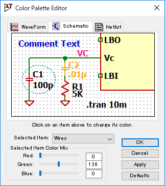
It is color-coded so that parts and wiring can be easily understood.
In addition, the background was set to white in order to make the contrast as clear as the WaveForm.
Netlist
I think that there is no problem with the default settings for Netlist. I have not made any color changes either.
Grid display on WaveForm
Since the WaveForm of LTspice XVII is easy to see, the grid is set to be displayed.
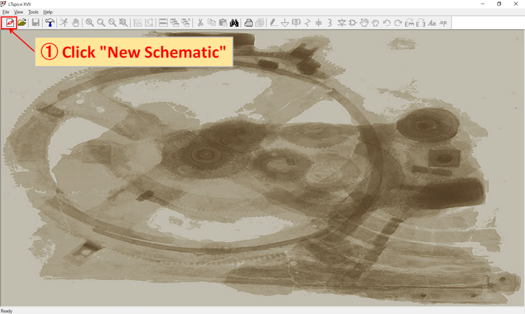
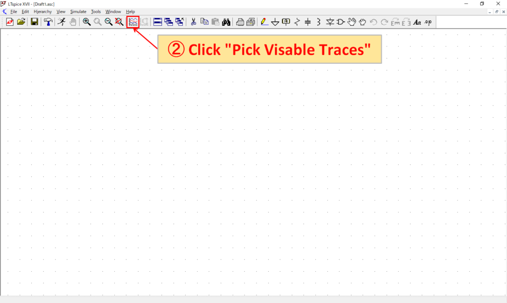
- Click the "New Schematic" icon on the toolbar to display the schematic editor.
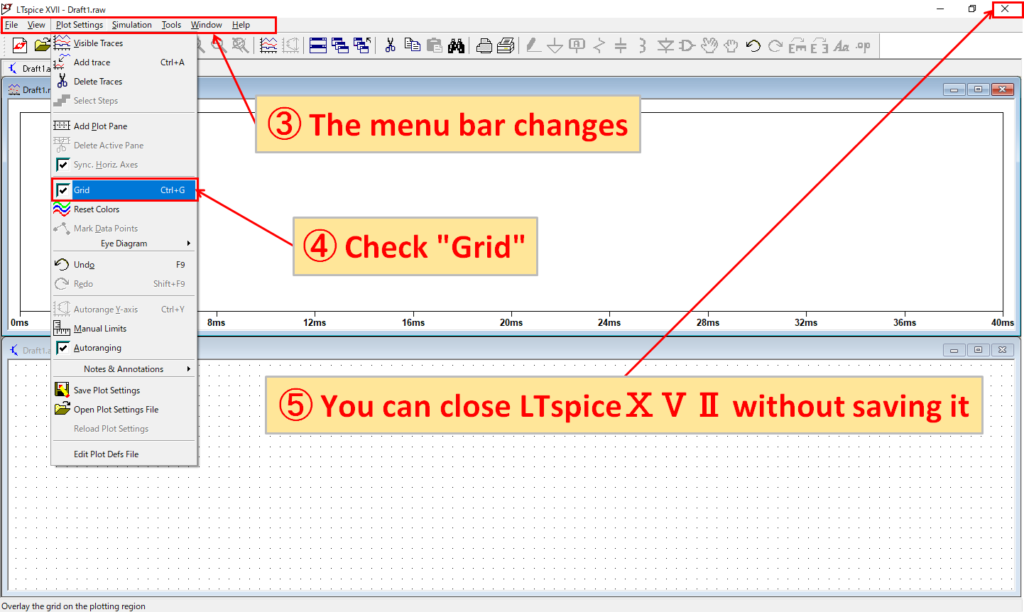
(It can also be displayed by clicking "File" -> "New Schematic" in the menu bar.) - Click the "Pick Visible Traces" icon on the toolbar to display the waveform graph.
(It can also be displayed by clicking "View" -> "Visible Traces" in the menu bar.) - The menu bar changes when the WaveForm is valid.
- Check "Plot Settings" -> "Grid" in the menu bar.
- You can see that the grid appears on the WaveForm when you run the simulation.
- After that, even if you close LTspice XVII without saving it, you will be able to display the grid from the next time.
How to use LTspice IV
Since LTspice II is freeware, we cannot receive support such as lectures on how to use it.
However, this site has posted a lot of detailed explanations on how to use LTspice IV, settings, circuit diagram creation, and simulation. Please see the following article for details.
