LTspice-Creating new Schematic symbol
In this article, we will explain in detail how to create schematic symbols.
If you can not use LTspice standard schematic symbols, you must create the schematic symbols yourself.
What if you can not use LTspice standard schematic symbols?
When adding a SPICE model (device model or subcircuit model) to LTspice, it is basically easy to use the LTspice standard schematic symbol.
(Although there are few cases, parts manufacturers may provide schematic symbols with the SPICE model.)
However, when it comes to a manufacturer's unique schematic symbol such as IC, it is almost impossible to cope with the LTspice standard schematic symbol.
In such cases, it is almost impossible to find free schematic symbols on the Internet, so you need to create your own schematic symbols.
Sub-circuit model getting
In this article, we will obtain the Analog Devices Quad SPST Switch "ADG1411" for the explanation.
Click the link below to go to the page where you can download SPICE models from the Analog Devices website.
When moving from the top page of the Analog Devices website, you can move in the order of DESIGN CENTER–>Simulation Models–>SPICE Models.
A list of SPICE models that can be downloaded is displayed as shown below.
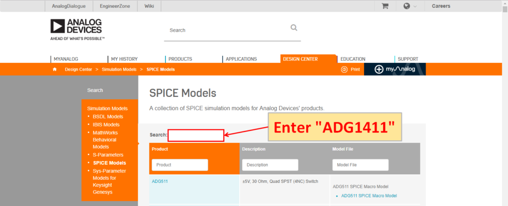
Enter “ADG1411” in “Search”.
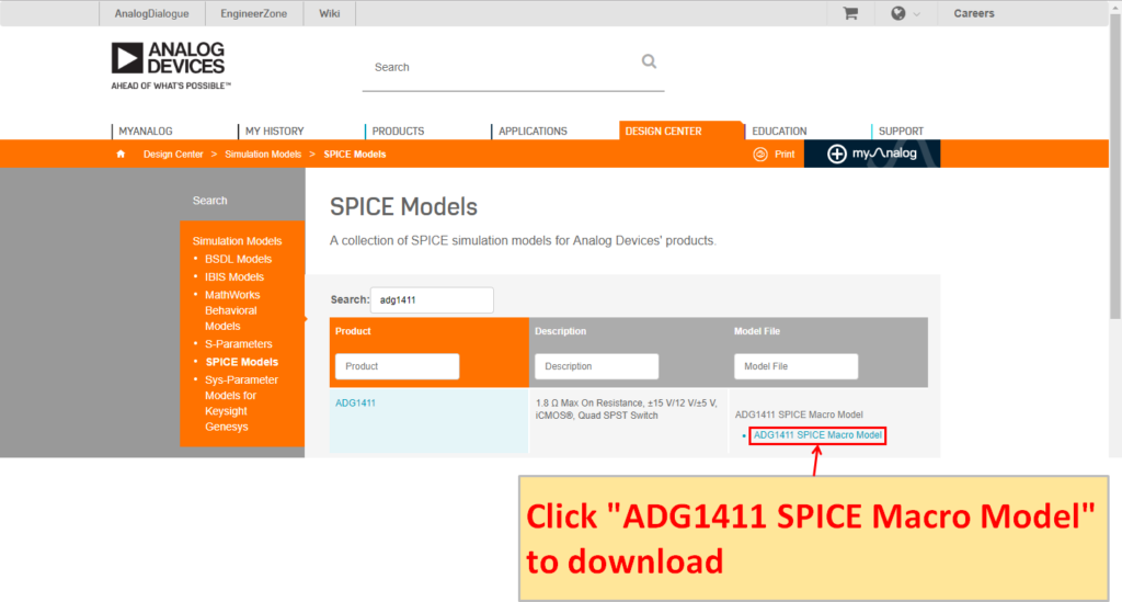
Click “ADG1411 SPICE Macro Model”.
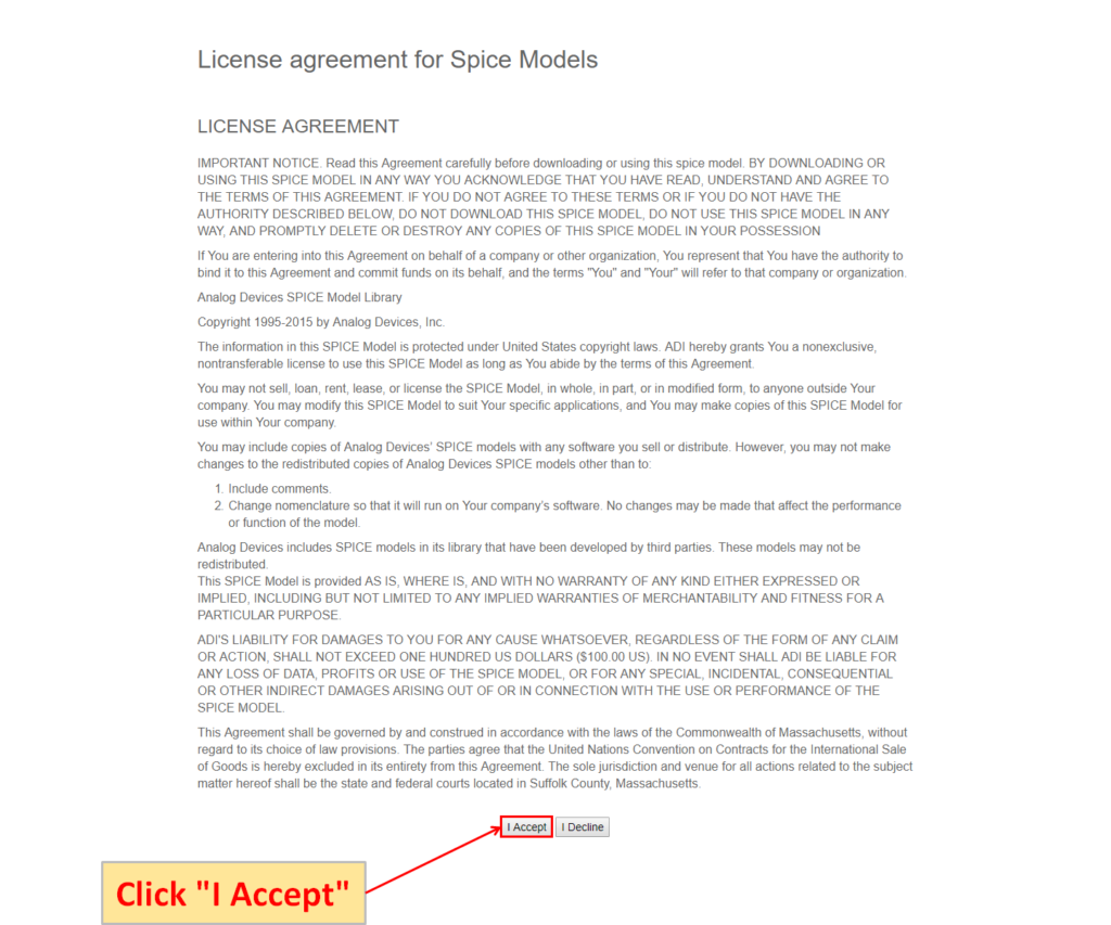
The "License agreement for Spice Models" screen is displayed. Click "I Accept" to start downloading.
Automatic creation of schematic symbols
LTspice has a function to automatically generate schematic symbols, and it is possible to easily generate schematic symbols with one click.
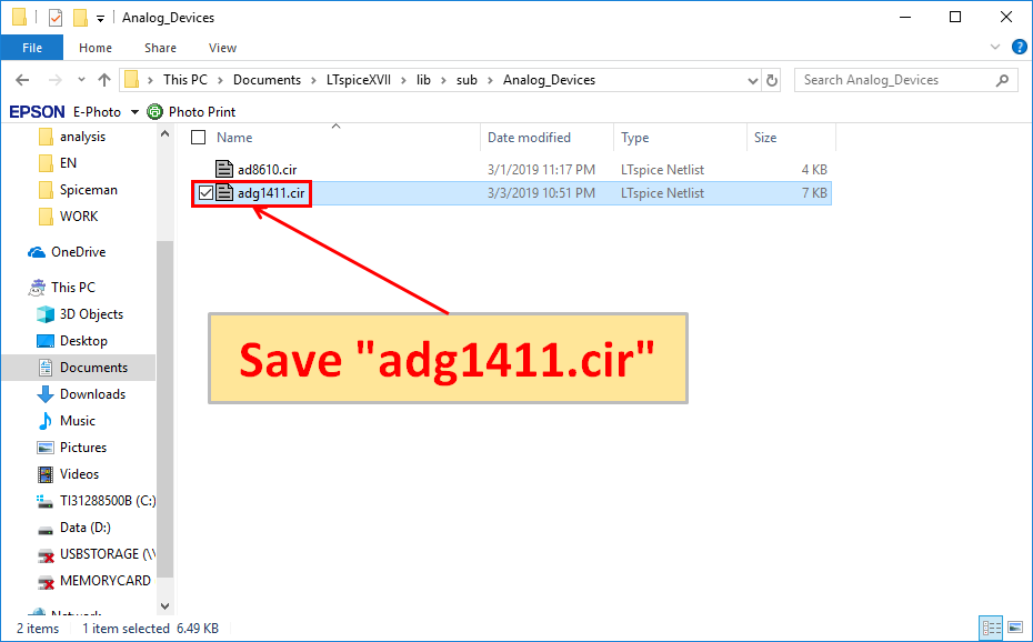
Save the downloaded "adg1411.cir" in "C:\Users\USER\Documents\LTspiceXVII\lib\sub\Analog_Devices".
※The folder "Analog_Devices" is created to make it easy to manage the subcircuit model in the following article.
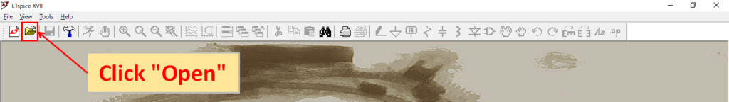
Start LTspice and click "Open".
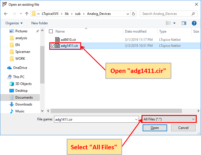
Select the file type "All Files" and open "adg1411.cir".
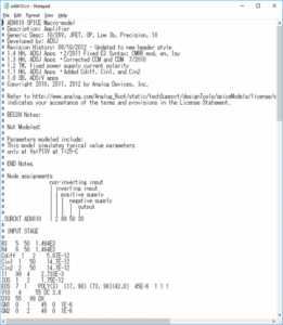
"adg1411.cir" opens as follows.
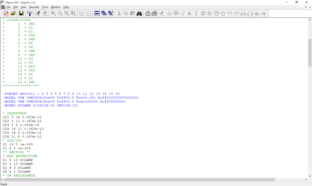
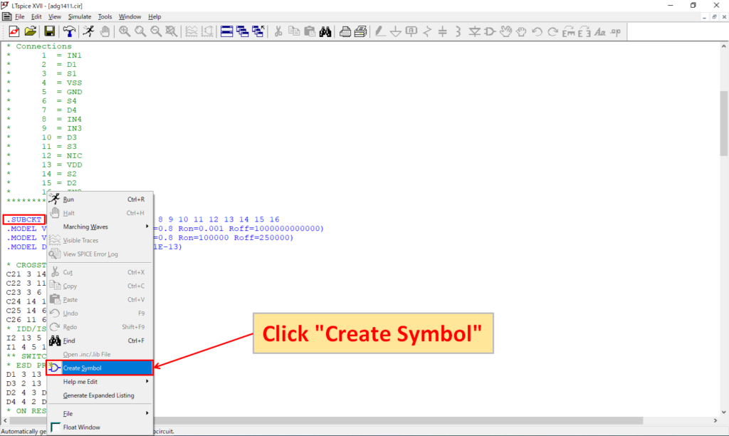
Right-click with mouse the .SUBCKT syntax described in "adg1411.cir" and click "Create Symbol".
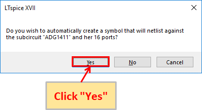
You will be asked if you want to create a schematic symbol of "adg 1411.cir" automatically, click "Yes".
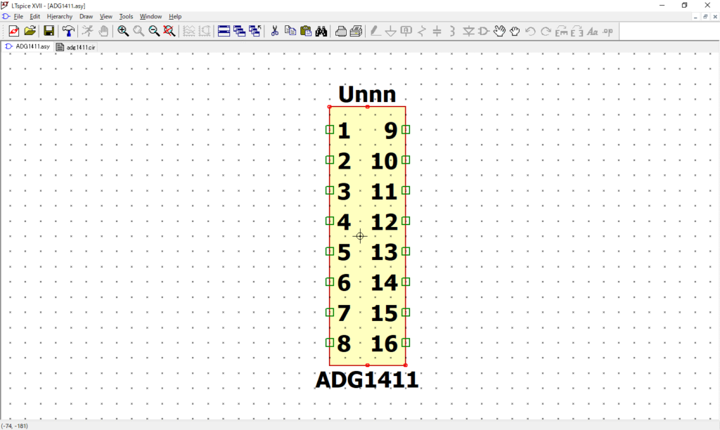
A schematic symbol of "adg1411.cir" is automatically created as follows.
In addition, the schematic symbol "ADG1411.asy" is automatically saved in "C:\Users\USER\Documents\LTspiceXVII\lib\sym\AutoGenerated" as shown below.
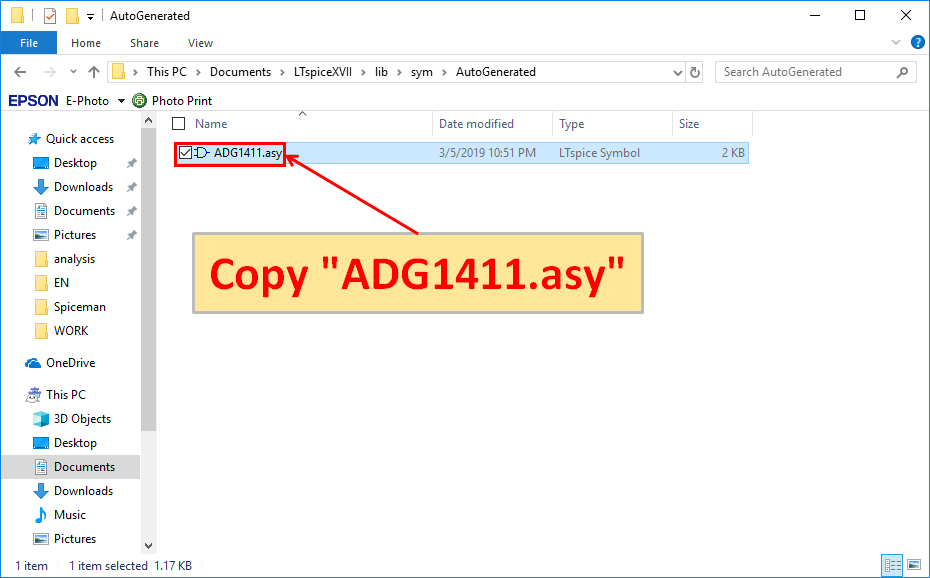
You should move "ADG 1411.asy" to any folder that is easy to manage.
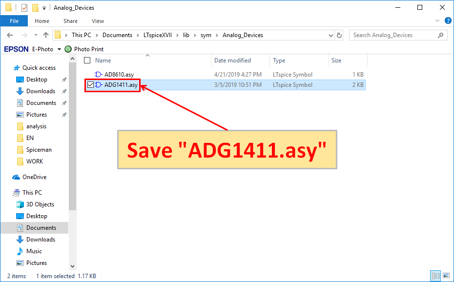
Save the copied "ADG1411.asy" in "C:\Users\USER\Documents\LTspiceXVII\lib\sym\Analog_Devices".
※The folder "Analog_Devices" is created in the following article to make it easy to manage schematic symbols.
However, there are problems with automatically created schematic symbols.
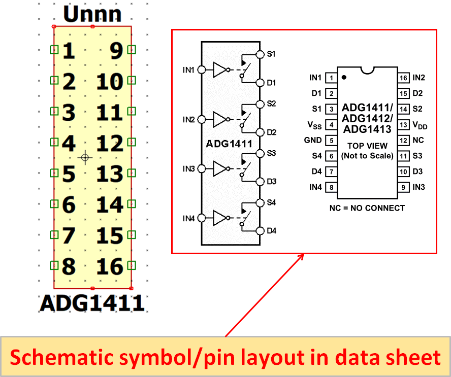
It is different from the schematic symbol of the data sheet because it just arranges the number pins automatically from the syntax of .SUBCKT. it is often very troublesome to wire on the schematic.
Therefore, it is better to correct the automatically created schematic symbols or create the schematic symbols manually from the beginning.
Manual creation of schematic symbols
Let's firmly remember how to create schematic symbols manually here.
Understanding how to create schematic symbols manually is also useful for correcting automatically created schematic symbols.
Symbol creation
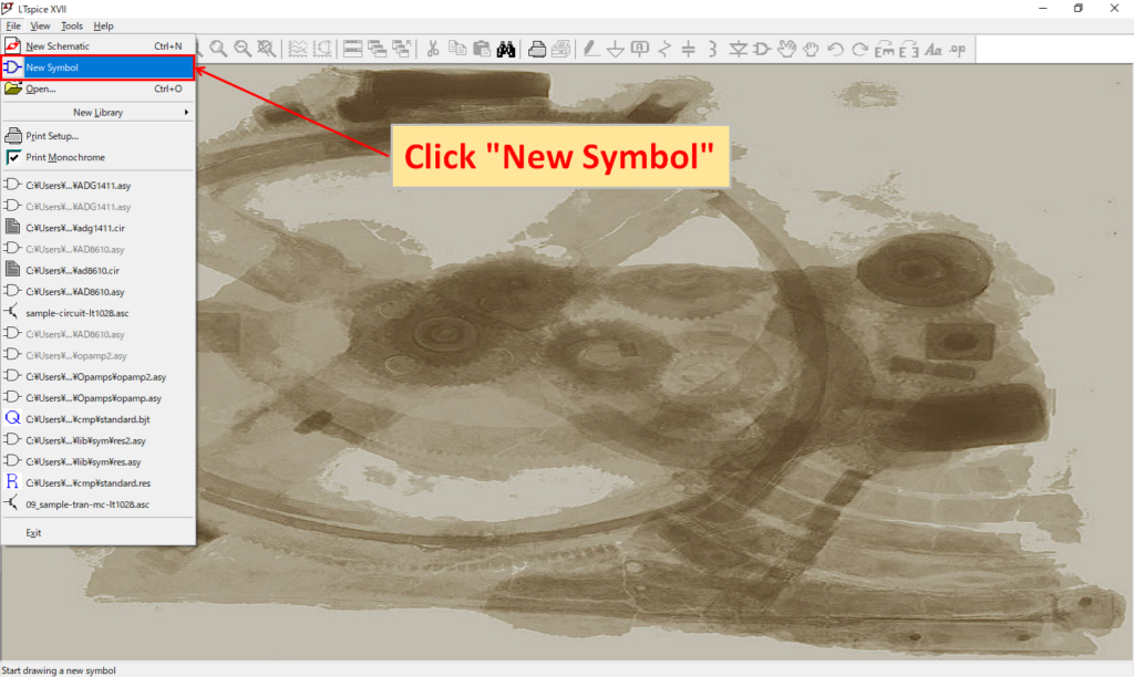
Start LTspice and click "File-New Symbol".
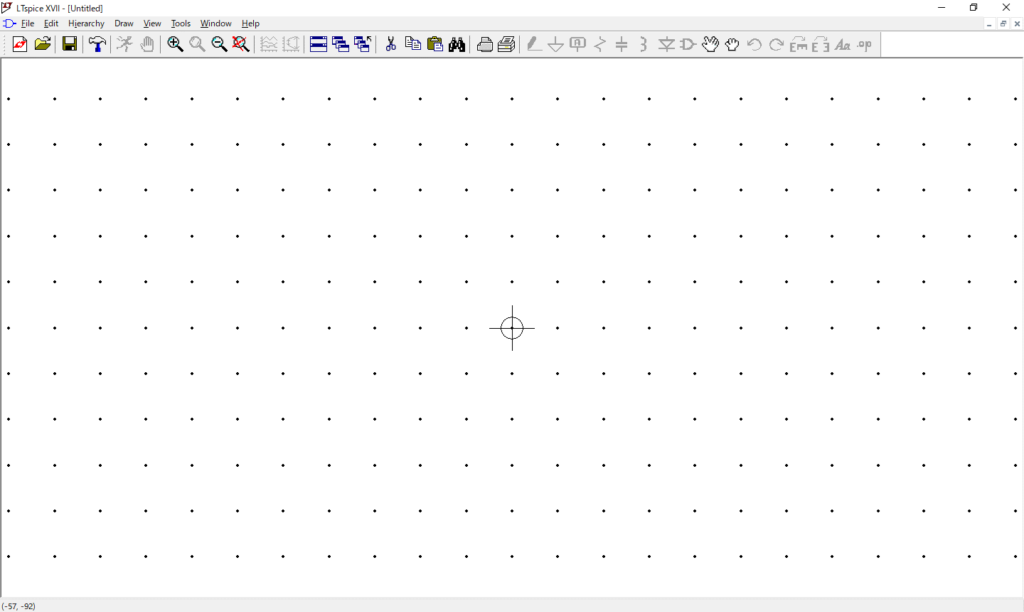
The schematic symbol editor is displayed. The circle and cross marks serve as reference points when moving parts when creating a schematic.
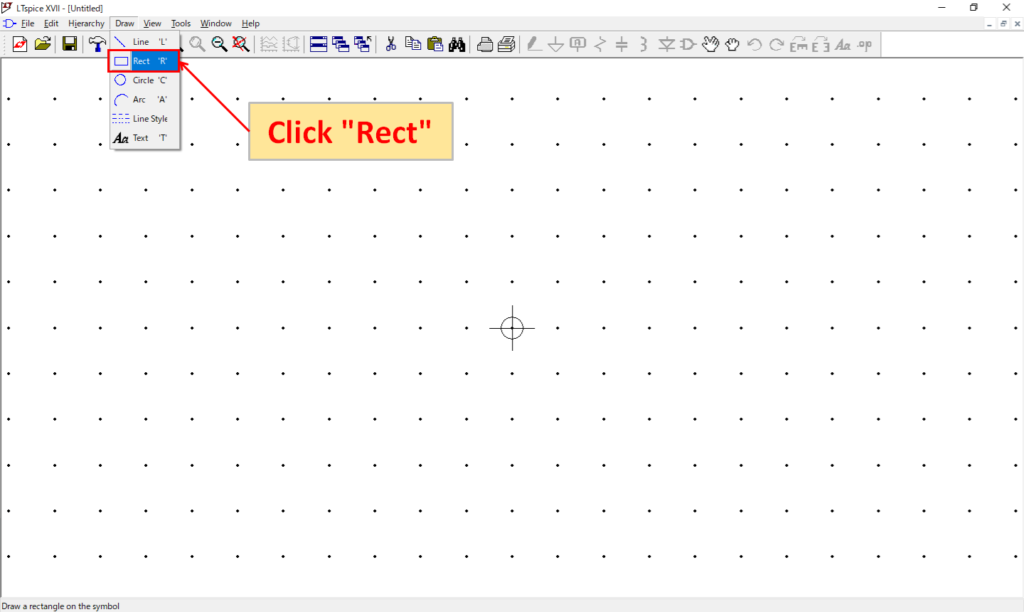
Select "Draw-Rect" and draw an outline of the schematic symbol with a square.
As you start from left click with the mouse on the schematic symbol editor, move the mouse diagonally to draw a rectangle.
If you left click with the mouse again, you can end it and complete the rectangle.
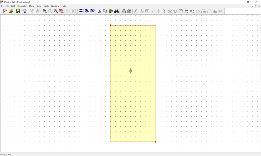
This time, I made a square so that the reference point(circle and cross mark) is almost centered.
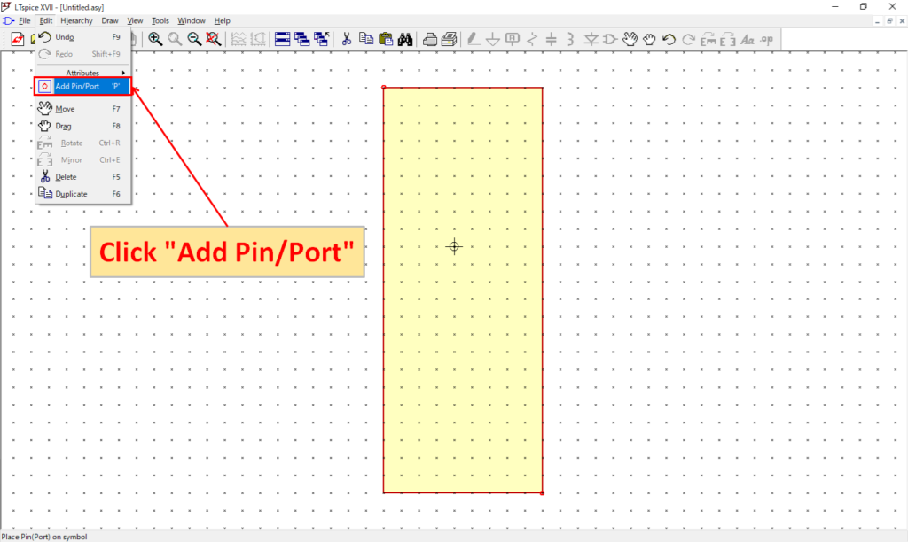
Select "Edit-Add Pin/Port" to edit the pin number.
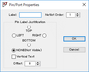
| Name | Explanation |
|---|---|
| Label | Pin name |
| Netlist Order | Node number |
| TOP/ LEFT/ RIGHT/ BOTTOM/ NONE(Not Visable) | Pin name position |
| Vertical Text | Make the pin name vertical |
| Offset | Pin and pin name offset |
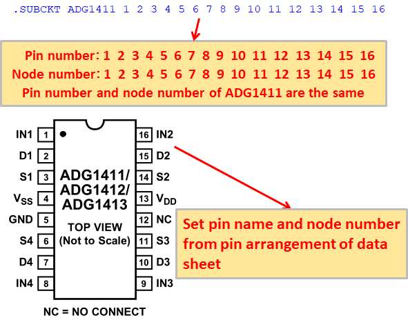
If you look at the .SUBCKT syntax of ADG1411, the pin numbers and node numbers of ADG1411 real parts are the same.
Therefore, let's set the pin name and node number as it is from the pin arrangement of the data sheet of ADG1411.
| Label | Netlist Order | TOP/ LEFT/ RIGHT/ BOTTOM/ NONE(Not Visable) |
|---|---|---|
| IN1 | 1 | LEFT |
| D1 | 2 | RIGHT |
| S1 | 3 | RIGHT |
| VSS | 4 | LEFT |
| GND | 5 | RIGHT |
| S4 | 6 | RIGHT |
| D4 | 7 | RIGHT |
| IN4 | 8 | LEFT |
| IN3 | 9 | LEFT |
| D3 | 10 | RIGHT |
| S3 | 11 | RIGHT |
| NC | 12 | RIGHT |
| VDD | 13 | LEFT |
| S2 | 14 | RIGHT |
| D2 | 15 | RIGHT |
| IN2 | 16 | LEFT |
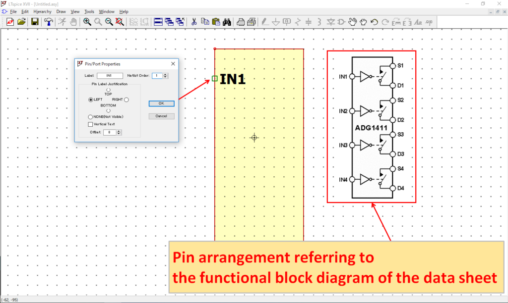
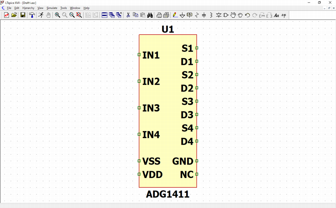
We will arrange the pins referring to the functional blocks of the ADG1411 data sheet.
Editing symbol attributes and saving the symbol
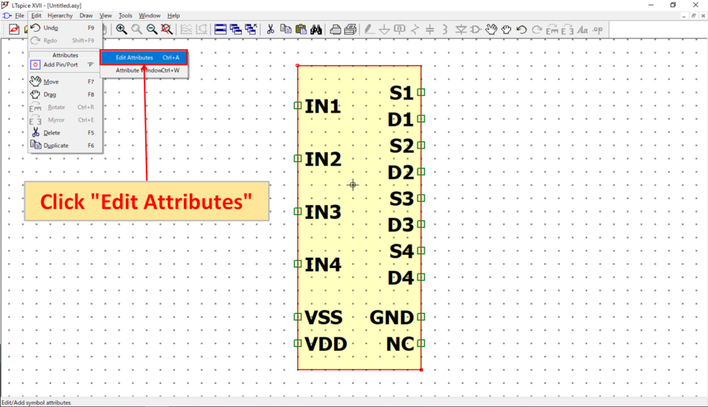
Open "Edit-Attributes-Edit Attributes" to edit symbol attributes.
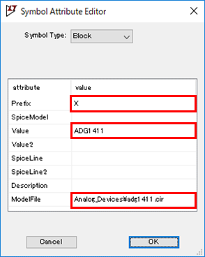
Set "Prefix:X, Value:ADG1411, Model File:Analog_Devices\adg1411.cir".
| Attributes | Explanation |
|---|---|
| Prefix | Schematic symbol prefix Resistance: R Capacitor: C Inductor: L Sub-circuit model: X ※ If it is a sub-circuit model, resistance, capacitor, and inductor become "X". |
| Spice Model | |
| Value | Name defined in the sub-circuit model file Example: ".SUBCKT AD8610" --> "AD8610" |
| Value2 | |
| Spice Line | Parameters other than Value |
| Spice Line2 | 〃 |
| Description | Schematic symbol description (Displayed on the symbol) |
| Model file | Sub-circuit model path |
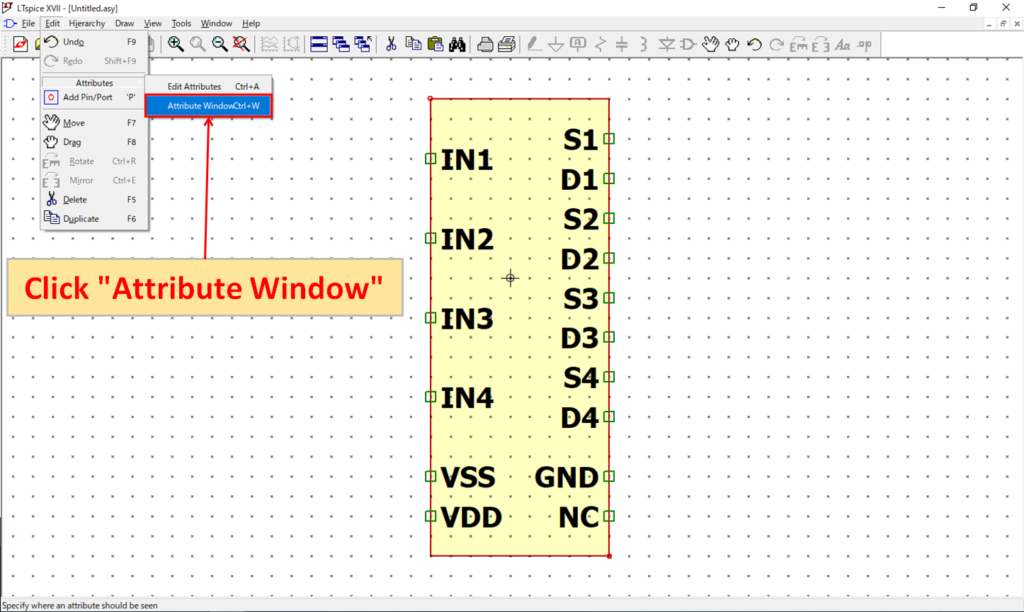
Open "Edit-Attributes-Attribute Window" to set the symbol information.
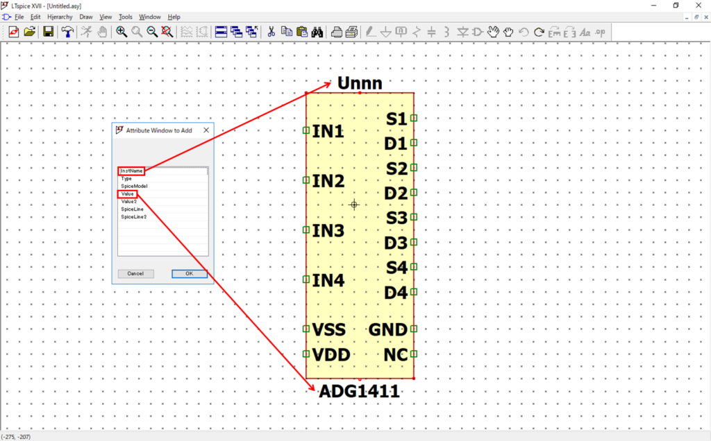
You can select the symbol information you want to display and click OK to place it.
In this article, we will place InstName(U1, U2, U3 …) and Value respectively.
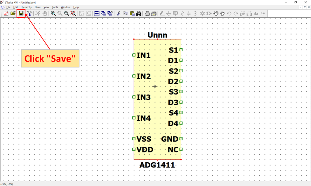
Now that you have done all of the manual creation of the schematic symbols, click "Save".
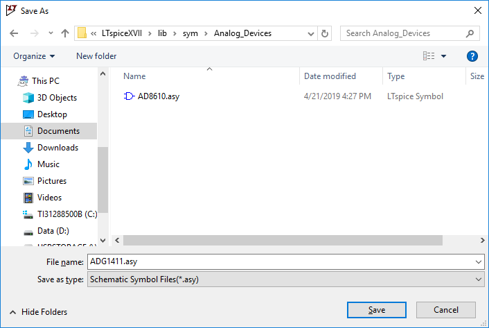
Save the renamed "ADG1411" to "C: \ Users \ USER \ Documents \ LTspiceXVII \ lib \ sym \ Analog_Devices".
※The folder "Analog_Devices" is created in the following article to make it easy to manage schematic symbols.
Confirm symbol
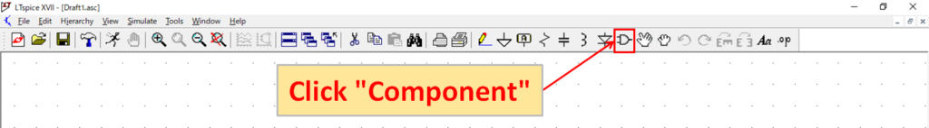
Open a new schematic editor in LTspice and click "Component".
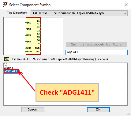
We were able to confirm "ADG1411" from "Select Component Symbol".
As a precaution, select "ADG1411" and click "OK" to place it on the schematic.
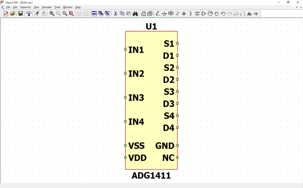
As with other parts, the "ADG1411" can be placed without any problem.
I have created the schematic symbols for ADG1411 from the beginning, but it is easier to create schematic symbols automatically and then fix them.
If you remember the schematic symbols manually, you won't have to bother with corrections from automatic creation.