LTspice-Addition of Sub-circuit model(.subckt)
In this article, we will explain in detail how to add sub-circuit model(.subckt) of SPICE models to LTspice.
It is possible to use other than SPICE models of Analog Devices(including Linear Technology) that are standard installed in LTspice.
Also, “Addition of Device model(.model)” is explained in the following article.
What kind of parts can be added by sub-circuit model?
The sub-circuit model is a SPICE model in which netlist notation starts with ".subckt" and is expressed by combining equivalent circuits.
Device models were limited to eight types: resistors, capacitors, inductors, ferrite beads, diodes, bipolar transistors, J-FETs, and MOS-FETs.
However, in the sub-circuit model, it is possible to create any part depending on the idea by combining equivalent circuits.
However, for LTspice beginners, it is difficult to create sub-circuit models by themselves, so it is realistic to first obtain and add sub-circuit models such as op-amps and ICs provided by parts manufacturers.
If you do not understand the meaning of the sub-circuit model itself, read the following article.
Sub-circuit model getting
To obtain a device model, it is easiest to obtain the device model provided by the parts manufacturer.
In this article, we will try to obtain the Analog Devices op-amp "AD8610" for explanation.
Click the link below to go to the page where you can download SPICE models from the Analog Devices website.
When moving from the top page of the Analog Devices website, you can move in the order of DESIGN CENTER-->Simulation Models-->SPICE Models.
A list of SPICE models that can be downloaded is displayed as shown below.
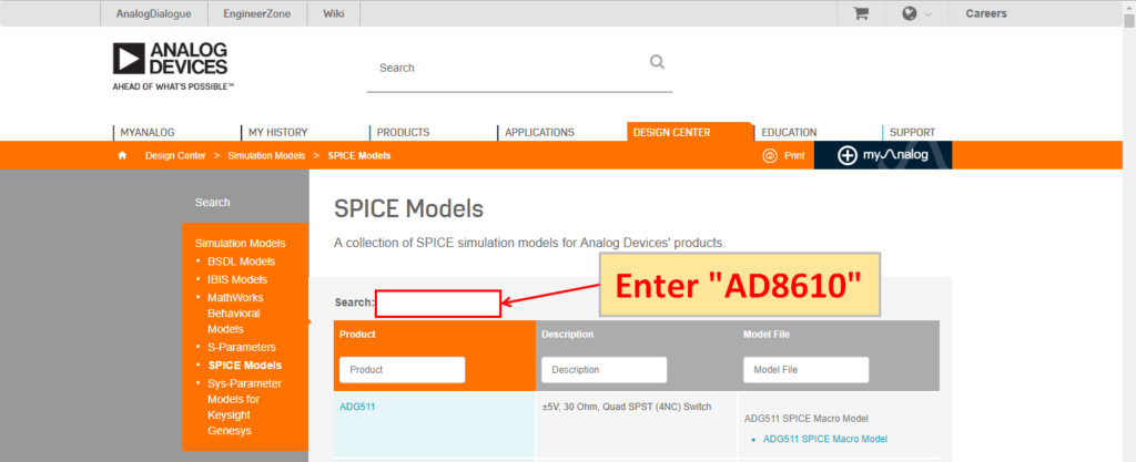
Enter "AD8610" in "Search".
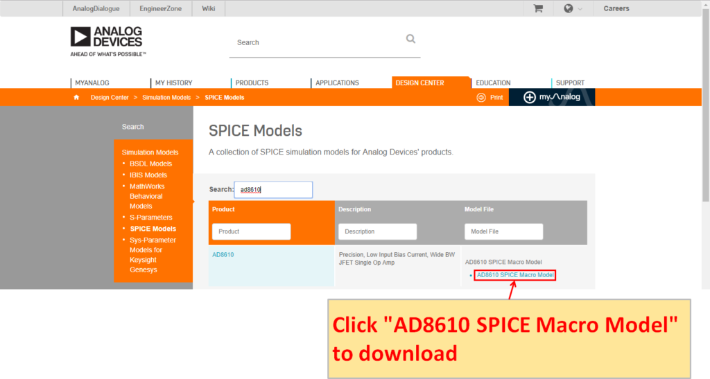
Click "AD8610 SPICE Macro Model".
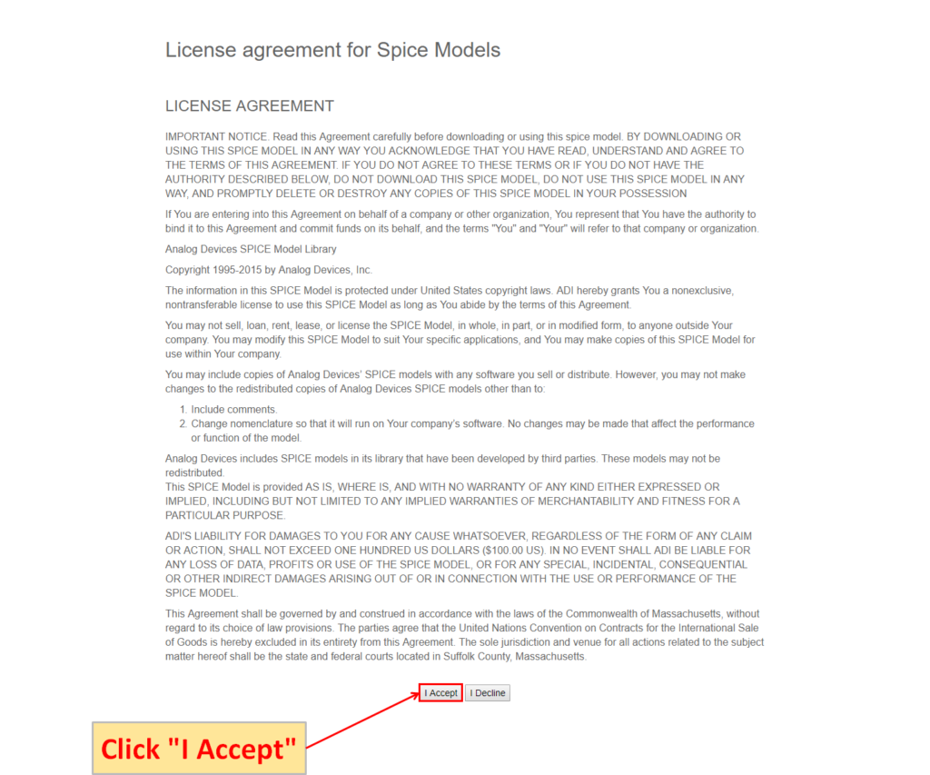
The "License agreement for Spice Models" screen is displayed. Click "I Accept" to start downloading.
Add sub-circuit model to LTspice
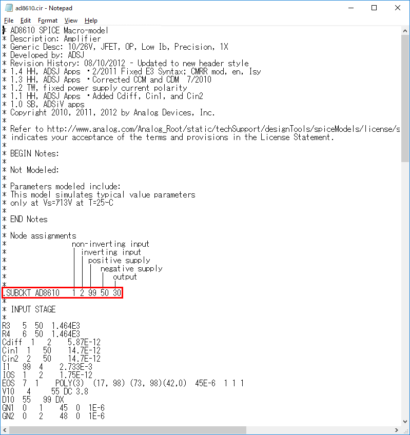
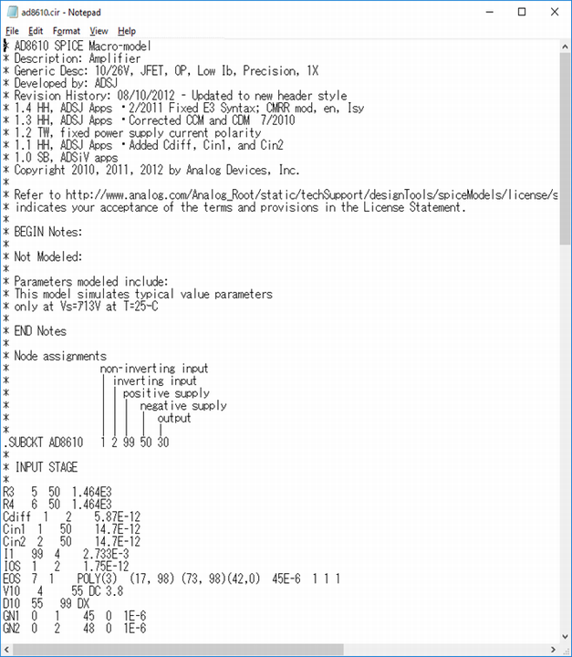
If you open the downloaded "ad8610.cir" in Notepad, you can see that it is a sub-circuit model because the description starts from .SUBCKT. We will add this sub-circuit model to LTspice.
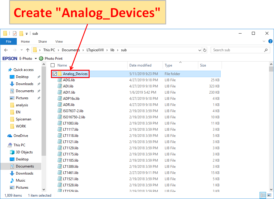
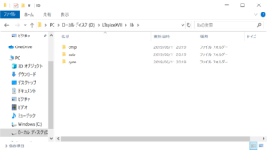
Create any folder in "C:\Users\USER\Documents\LTspiceXVII\lib\sub".
LTspice updates files with regular updates.
Therefore, if you add a sub-circuit model in the sub folder, you will not know the location of the file you added.
Therefore, it is easier to manage by creating an arbitrary folder and adding a sub-circuit model to it.
The folder name may be anything, but in this site we will create folders by manufacturer, so we will create "Analog_Devices".
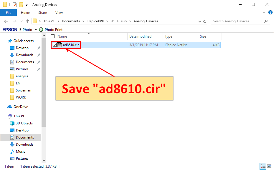
Save the downloaded "ad8610.cir" in "C:\Users\USER\Documents\LTspiceXVII\lib\sub\Analog_Devices".
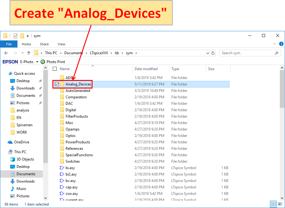
Create an arbitrary folder in "C:\Users\USER\Documents\LTspiceXVII\lib\sym".
Similarly, create "Analog_Devices" as a folder according to manufacturer.
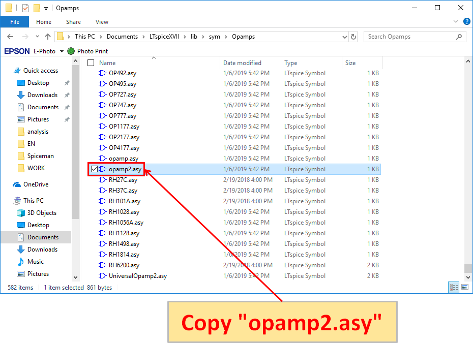
Because it is difficult to create schematic symbols, we will use the standard prepared schematic symbols.
First, copy the opamp's schematic symbol "opamp2.asy" from "C:\Users\USER\Documents\LTspiceXVII\lib\sym".
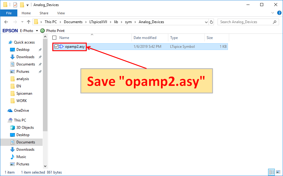
Save the copied "opamp2.asy" to "C:\Users\USER\Documents\LTspiceXVII\lib\sym".
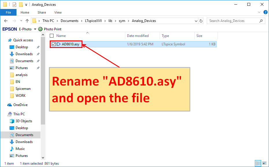
Rename "opamp2.asy" saved in "C:\Users\USER\Documents\LTspiceXVII\lib\sym\Analog_Devices" to "AD8610.asy".
After changing the name, open the file "AD8610.asy".
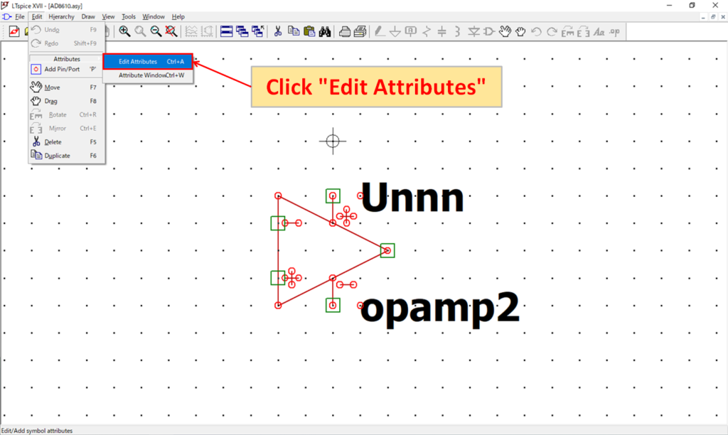
Launch LTspice and open the file "AD8610.asy". Click "Edit-Edit Attributes" to open the symbol attribute edit screen.
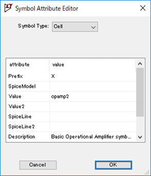
The detailed meaning of each attribute of "Edit-Edit Attributes" is as follows.
| Attributes | Explanation |
|---|---|
| Prefix | Schematic symbol prefix Resistance: R Capacitor: C Inductor: L Sub-circuit model: X ※ If it is a sub-circuit model, resistance, capacitor, and inductor become "X". |
| Spice Model | |
| Value | Name defined in the sub-circuit model file Example: ".SUBCKT AD8610" --> "AD8610" |
| Value2 | |
| Spice Line | Parameters other than Value |
| Spice Line2 | 〃 |
| Description | Schematic symbol description (Displayed on the symbol) |
| Model file | Sub-circuit model path |
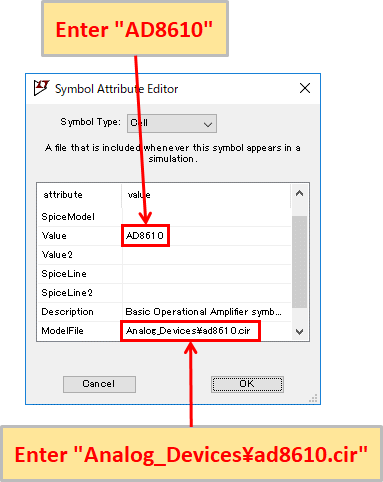
Associate the sub-circuit model "ad8610.cir" with the schematic symbol "AD8610.asy".
Change "Value" to "AD8610" which is the same as the ad8610.cir sub-circuit model name, and change "Model File" to "Analog_Devices\ad8610.cir" of the path where ad8610.cir is stored.
In this article, the path of the sub-circuit model is set in "Model File", but it can also be defined in "Control Panel"-"Sym. & Lib. Search Paths"-"Library Search Path [*]" .
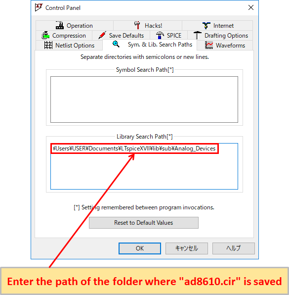
Take “AD8610” described in this article as an example, enter the path of the folder("C:\Users\USER\Documents\LTspiceXVII\lib\sub\Maker\Analog_Devices") where “ad8610.cir” is stored in “Library Search Path [*]”.
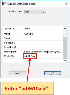
Then, in the "Symbol Attribute Editor"-"Model File" of "AD8610.asy", enter "ad8610.cir" as the file name of the sub-circuit model to be associated with AD8610.asy.
Later, if there is a possibility that the storage location of the sub-circuit model file may change, it is convenient because it can be changed collectively by only modifying the path of the folder input to “Library Search Path [*]”.
In addition, some of the parts manufacturers that offer LTspice SPICE models also distribute schematic symbols along with SPICE models(device models and sub-circuit models).
In such a case, the file name of the sub-circuit model to be associated is already entered in the "Symbol Attribute Editor"-"Model File" of the schematic symbol.
Therefore, SPICE models can be added simply by defining the location of the folder where the sub-circuit model is saved in "Control Panel"-"Sym. & Lib. Search Paths"-"Library Search Path [*]".
In this article, the path of the sub-circuit model is set by "Model File", but it can also be defined on the schematic.
For example, in this case, write ".lib Analog_Devices\ad8610.cir" in the SPICE directive and place it on the schematic using AD8610.
However, this method is troublesome because it has to place the .lib syntax in the schematic one by one. After all, it is better to set in "Symbol Atribute Editor".
※ It works with “.inc” instead of “.lib”.
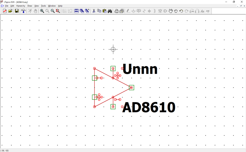
The schematic symbol has now been changed to "AD8610".
Next, check if the pin arrangement matches in the sub-circuit model "ad8610.cir" and the schematic symbol "AD8610.asy".
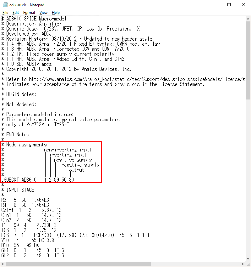
If you open "ad8610.cir" in Notepad, the pins are Non-Inverting Input(+ input), Inverting Input(-input), Positive supply(+ power), negative supply(-power), output(output) in this order. You can see that the numbers are in place.
Therefore, the AD8610's output/input, power supply and pin numbers correspond as follows. This is the same as the pin number of the op-amp's schematic symbol stored as standard in LTdpice.
| AD8610 | Pin Number |
|---|---|
| non-Inverting Input | 1 |
| inverting Input | 2 |
| positive supply | 3 |
| negative supply | 4 |
| output | 5 |
*Note that this is not the pin number of the AD8610 actual part.
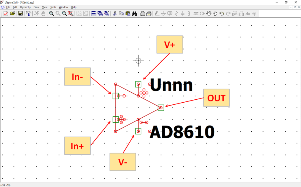
Returning to the schematic symbol "AD8610" and right-clicking each pin with a mouse, the "Pin/Port Properties" screen opens and you can check whether the pin numbers of the sub-circuit model and the schematic symbol match.
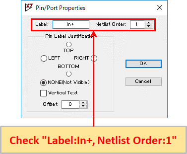
If you right-click In+(+ input) with the mouse, you can see that the “Netlist Order(pin number)” of the schematic symbol is “1”, which matches the sub-circuit model.
Similarly, let's check other Netlist Orders.
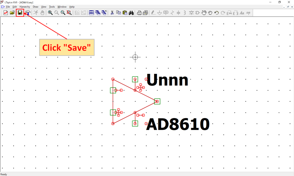
Save after confirming that the pin numbers match. This is the end of adding sub-circuit models.
Confirm the added sub-circuit model

Open a new schematic editor in LTspice and click Component.
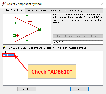
We were able to confirm "AD8610" from "Select Component Symbol".
As a precaution, select "AD8610" and click "OK" to place it on the schematic.
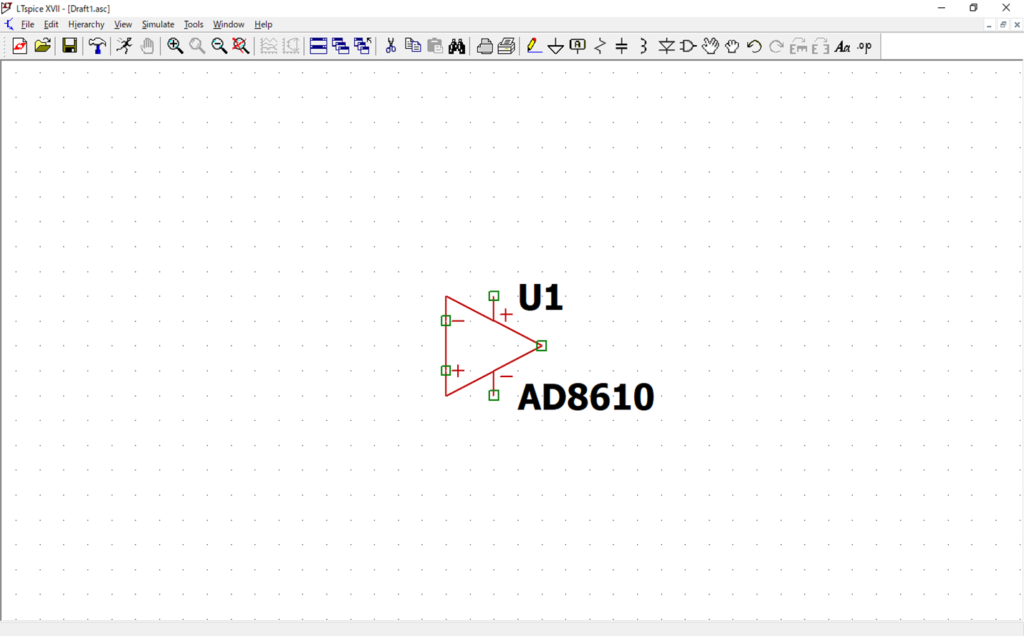
As with other parts, the AD8610 can be placed without any problems.